
Hospitals use the phrase “source plant test” for very different equipment: liquid oxygen systems, cylinder manifolds, medical-air compressors, synthetic-air sources and medical vacuum plants. These systems do not share one operating principle, one fault mode or one set of acceptance evidence.
The 2026 Scottish SHTM 02-01 distinguishes A9 liquid oxygen plant, A10 medical gas manifolds, A11 medical/surgical air plant, A12 synthetic air systems and A13 medical vacuum plant. The form selection should follow the actual installed source, not whichever certificate is easiest to retrieve.
Separate source product duty from installed delivery
A manufacturer can demonstrate factory output under declared conditions, but the installed source also depends on its piping, controls, alarm receiving, electrical service, changeover arrangements, room conditions and clinical demand.
The project should specify both factory performance evidence and the particular installed system acceptance tests. ISO 7396-1:2016 addresses pipeline sources and connected distribution, while each installed source also involves manufacturer-specific safety requirements.
Family-specific source evidence map
| Source type | Key system questions | Typical record |
|---|---|---|
| Liquid oxygen source | Storage/vaporization configuration, availability, supplied pressure and safe site conditions | A9 |
| Cylinder manifold | Bank configuration, automatic/manual changeover, reserve and alarms | A10 |
| Medical/surgical air | Compressor/dryer treatment, supply performance, air quality and alerts | A11 |
| Synthetic medical air | Correct proportioning/source configuration, verified composition and continuity | A12 |
| Medical vacuum | Vacuum plant effective duty, receiver/filter arrangement, standby and controls | A13 |
This is an index of engineering evidence—not a substitute for the forms' actual technical tests or test values.
Do not confuse multiple motor units with resilience
Two compressors or vacuum pumps may share a critical control or power path. A manifold with two banks may have inadequate changeover capacity. The approved reliability scenario must include any common dependencies and the intended maintenance state.
The hospital design authority should specify the degraded operating cases and the witnessing plan before vendors submit equipment.
Example: air plant that passes a mechanical FAT
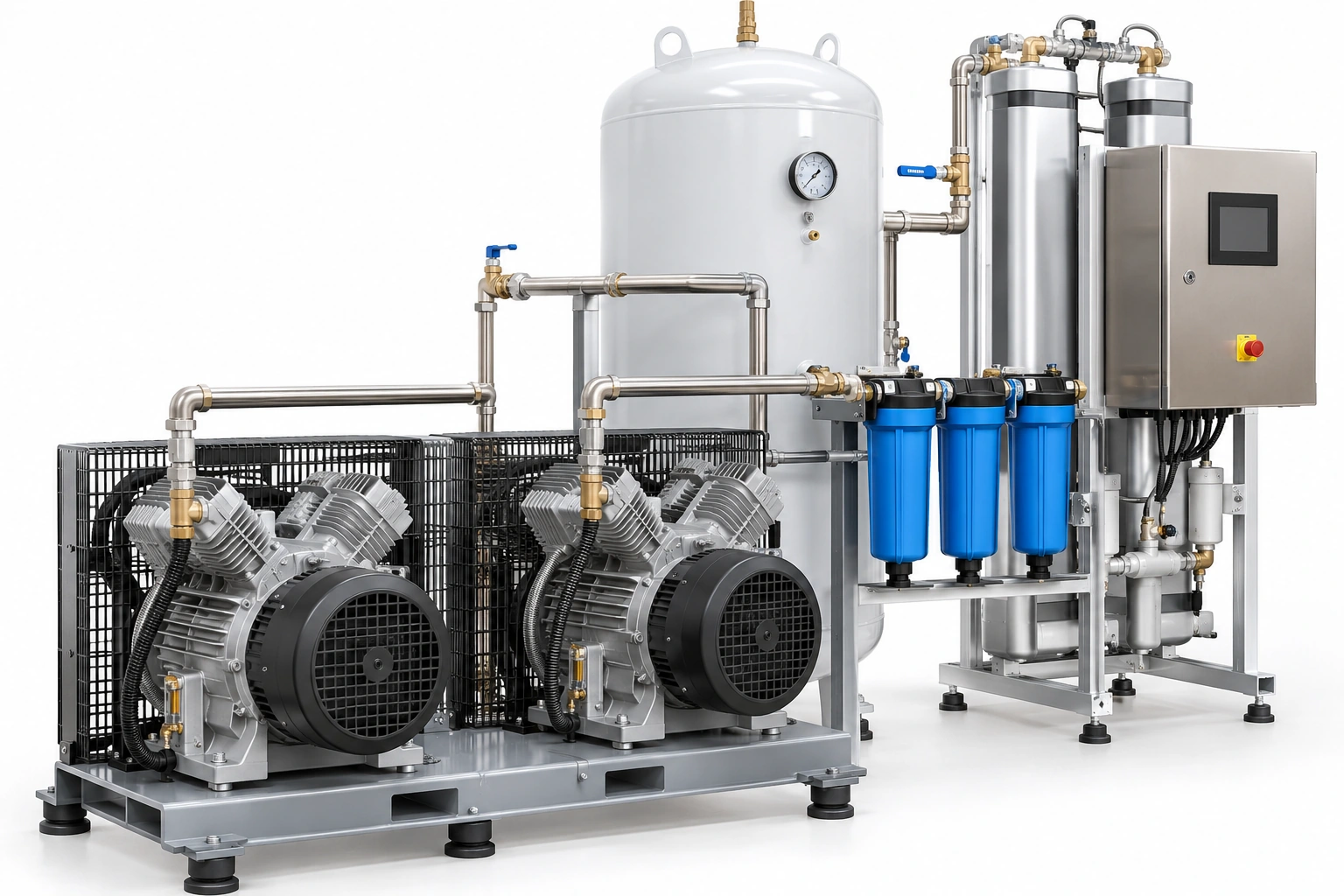
A medical-air compressor passes its mechanical factory test, and the seller submits a catalogue statement of filtration capability. The actual hospital installation includes dryer, receiver, treatment stages, alarms and downstream quality testing not included in the factory demonstration.
A mechanical FAT is only one input. The project still needs accepted site plant tests and relevant air quality evidence; the nominated air supply must be assessed as a complete source system.
Require conditions behind performance figures
Manufacturers may report free-air displacement, delivered flow, pressure or vacuum at different ambient and measurement conditions. Compare curves and duty only where measurement bases and required operating points are made equivalent.
The plant model, serial and control revision should appear both on the factory record and the as-installed test certificate. Equipment substitutions after approval require a documented design and acceptance review.
Integrate source and alarm records
A source plant test can reveal acceptable normal operation but says less about what a ward or staffed central alarm panel will display after a relevant fault. Link plant forms with the applicable A14/A15 area/central alarm records and confirm any dependent source-specific tests.
An up-to-date P&ID and I/O list makes it possible to identify test points accurately.
Avoid site-independent numerical recipes
No single online pressure, vacuum or flow target is universally appropriate to all countries and source configurations. Actual accepted criteria come from the adopted code, clinical duty schedule, qualified designer and manufacturer's instructions.
NHS England HTM 02-01 (2026) provides design, validation and operational guidance, but a project outside that jurisdiction must document its own adoption basis.
Vendor and BWC scope
BWC Medgas provides selected manifold components, pressure regulators and gauges and medical gas valves. Complete plant design, installation and commissioning are distinct specialist scopes.
The plant RFQ should include the applicable A9–A13 evidence, system drawings, spare kits, control logic, factory tests and installed commissioning responsibilities.
Submit an approved source-component or manifold-parts schedule to BWC Medgas.
Frequently asked questions
Do all hospital source plants use the same acceptance sheet?
No. The Scottish 2026 form set separates source technologies.
Can a supplier's rated pump or compressor output prove installed hospital duty?
No. Verify actual equipment and system performance under the accepted conditions.