
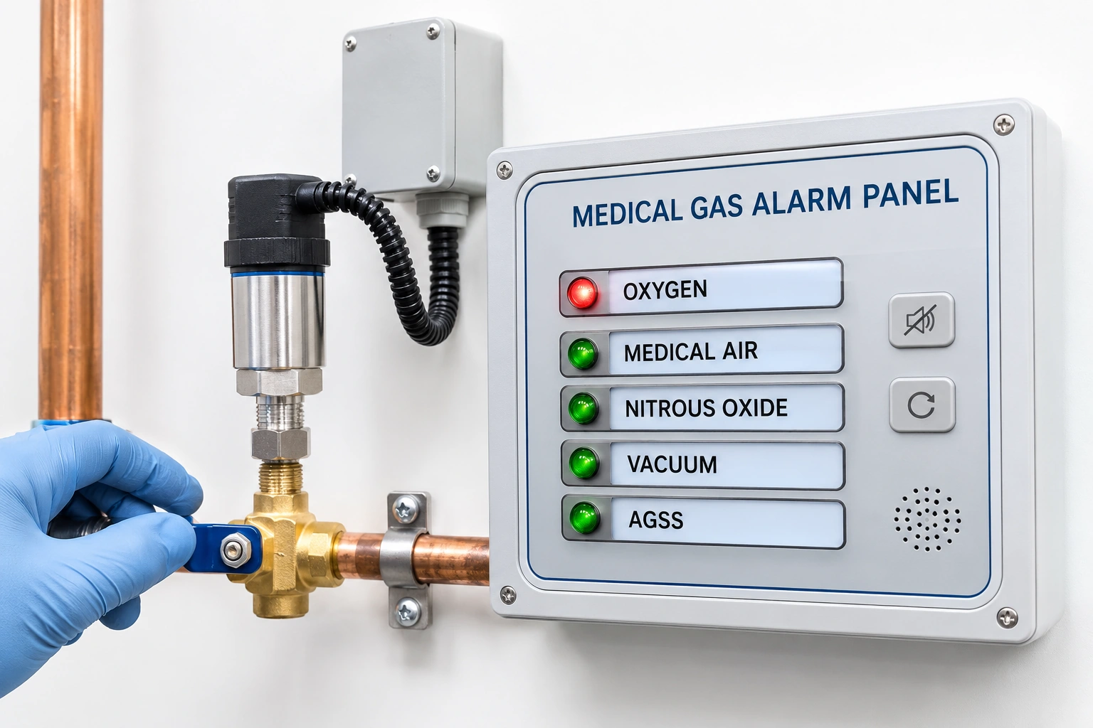
A polished alarm panel can display correct lettering and the right number of LEDs without proving that a source event reaches the designated staffed location. The proper engineering question is whether the physical condition, measured point, message and clinical/estates receiving route have all been verified together.
The Scottish 2026 SHTM 02-01 distinguishes Form A14 — Area alarm panel test and Form A15 — Central alarm panel test. These are separate responsibilities even when both are served by networked equipment or integrated into one building automation system.
Construct the alarm identity first
For each source, zone or service condition, assign a point ID, the gas/vacuum service, physical sensor or status contact, approved trigger meaning, expected receiving panel, display label and responsible hospital role.
Do not call an alarm “oxygen fault” without stating whether it concerns plant supply availability, a local area pressure condition, an instrument failure or another specific approved event.
Cause-and-effect acceptance schedule
| Field | Evidence requirement | Result location |
|---|---|---|
| Source point | Asset and sensor identity on the approved P&ID | Source schedule |
| Event definition | Physical meaning of the approved abnormal condition | Cause/effect matrix |
| Receiving panel | Exact area/central panel position and panel ID | Alarm map |
| Text/visual cue | Unambiguous service and area information | Display specification |
| Acknowledgement | Defined permitted behavior and event retention | Functional description |
| Communication fault | Appropriate response to loss of signal or stale data | Fault test plan |
| Power continuity | Approved normal/backup arrangements where applicable | Electrical dossier |
| Witness | Actual tested route and sign-off | A14/A15 record |
A site test should use a qualified method to establish the true system chain rather than relying solely on the controller manufacturer's demo screen.
Distinguish local and central responsibilities
Area alarms may be directed at particular clinical locations, while central alarms may be received by an estates or continuously staffed operation. Their purposes and response plans differ by hospital, so the receiving point needs a named owner.
A display integrated with building management is only part of the picture. The facility must confirm whether the specified MGPS alarm functions and resilience remain available if the general building network is interrupted.
Example: controller reports but receiving panel stays silent
The manifold controller logs a genuine change of state and shows it as abnormal on its local display. The theatre alarm panel reports normal because its mapping uses an obsolete software address from the previous plant.
A successful source-controller test is not an A14/A15 end-to-end acceptance. The project needs an approved signal-path correction and witnessed retest of each affected receiving point.
Version and calibration management
Record controller and receiver software versions, I/O or network mapping revisions, sensor calibration references and test instrument conditions. If a firmware update changes event routing after witness testing, the project must assess required retests.
A corrected screenshot should not overwrite an earlier nonconformance. Retain an identifiable defect history and final accepted configuration.
Clinical coordination in occupied facilities
Alarm tests must not create false clinical confidence or interrupt service. Hospital leadership should approve the test window, communications, competent testers and procedure for restoring normal monitoring.
ISO 7396-1:2016 covers medical gas and vacuum system alarms and commissioning. NHS England HTM 02-01 (2026) provides current operational management alongside installation/validation. Adopted regional code and healthcare policy determine the exact requirements.
Procurement before installation
Request sensor point lists, configurable event descriptions, panel topology, fault supervision, interface protocol, acceptance reports, spares and maintenance support. Buying on the number of inputs alone misses the communication and service responsibilities.
BWC Medgas supplies selected medical gas alarm systems, zone valves and related components to an approved system architecture. Hospital end-to-end verification is done by the appointed qualified team.
Send the approved alarm point and panel schedule to BWC Medgas.
Frequently asked questions
Does a working local manifold alarm prove the remote ward receives the event?
No. The complete source-to-receiver path needs its own accepted test.
Can an A14 area alarm sheet be used as an A15 central alarm certificate?
No. Each addresses a different nominated receiving function.