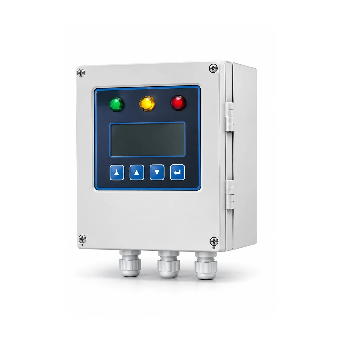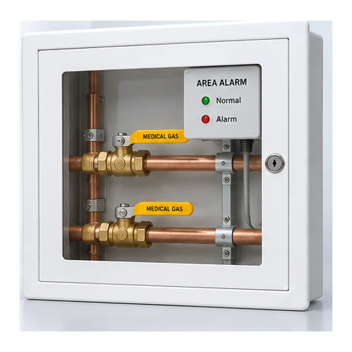

A medical gas alarm can be healthy while the network is available and the mains supply is normal, yet the same design may have a hidden dependency that makes the necessary warning unavailable during a fault. A modern touchscreen or cloud dashboard cannot by itself prove continuity of the required medical-gas safety notification.
A failure-mode and resilience review should identify how necessary functions remain available or fail visibly when a supply, device, cable, communications path or configuration element is impaired. The project's qualified designer must determine actual resilience requirements and approved test conditions.
Map dependencies, not just devices
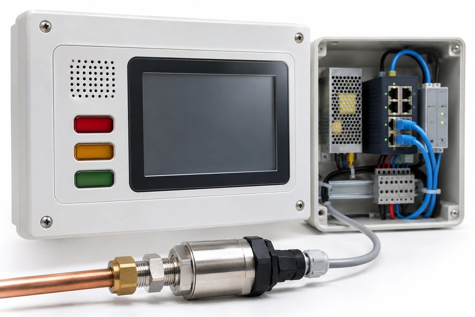
Start from each monitoring point and trace the full chain: physical sensor or plant contact; measurement/electrical supply; local controller; cable/network connection; receiving panel; sound/visual indication; and staffed response location.
For each segment identify whether it depends on one power supply, one network switch, one controller, one building system or one communication link. Distinguish independent paths from software views that ultimately depend on the same failed element.
ISO 7396-1:2016 establishes system-level monitoring/alarm context, while UK HTM/SHTM and adopted US code set actual project requirements.
Create a failure-mode table
| Potential failure | Engineering question | Evidence to retain |
|---|---|---|
| Local power loss | Which required indication remains or fails visibly? | Approved power and alarm design |
| Alarm controller failure | How is loss of function made apparent? | Controller fault specification |
| Disconnected sensor | Can the receiver distinguish fault from normal value? | Supervision and test record |
| Network/communication loss | Which receiving locations retain required information? | Architecture and site verification |
| Display or sounder fault | What is the defined fault indication or maintenance response? | Function/test schedule |
| Time or config error | Can wrong timestamps/messages mislead operators? | Configuration control |
| Remote/cloud loss | Are mandatory on-site warnings independent as designed? | Alarm boundary drawing |
The table is a design-review prompt. It does not prescribe a universal battery duration, test voltage or communication timeout.
Evaluate independence carefully
Two screens on one data gateway are not two independent alarm systems. If the same gateway or power supply fails, both may become unavailable simultaneously.
Document the real architecture with component and interface references rather than vague words like “fully redundant.” If a design relies on alternative paths, identify how independence is established and tested under safe approved circumstances.
A distributed system may satisfy the project design, but that must be demonstrated by its actual topology and required functional evidence.
Do not equate BMS visibility with alarm continuity
A building management system can be valuable for maintenance information and trend analysis. It should not automatically replace required healthcare alarm panels or staffed receiving points. Evaluate whether it is supplementary or part of the approved safety architecture.
For network-connected systems, [NIST SP 800-82 Rev. 3 (2023)](https://csrc.nist.gov/pubs/sp/800/82/r3/final) describes OT security principles relevant to availability and safe system integration. A new revision was only in public draft as of November 2026.
Document fault awareness and restoration
Design requirements should state what authorized staff see when a communication link fails, how a fault is acknowledged, where diagnostics are recorded, and how recovery is confirmed.
Restoring power or a network connection does not automatically establish that every original alarm point, display mapping and response path is healthy. Site procedures may require qualified checks after the event.
Maintain records of outage, affected functions, contingency communications, corrective work and final accepted return to service.
Illustrative dependency risk
A central alarm repeater receives several oxygen source signals via a single network appliance installed in an unrelated IT cabinet. During a network change, the repeater shows its usual interface but no longer receives live updates. The system should have a design-approved way to identify that loss and support the required clinical/engineering response.
The review should not instruct anyone to disconnect the link while a hospital is operating; authorized specialists determine safe testing.
Procurement acceptance questions
Ask vendors for power requirements, supported fault indications, communications supervision, architecture diagrams, local/central receiving behavior, restoration/restart behavior, firmware configuration, approved testing capability, alarm event handling and maintenance documentation.
Require clear included/excluded hardware lists. A vendor's “battery backup available” brochure is not enough to prove it is included in the quoted system.
BWC Medgas component supply
BWC can provide selected medical-gas alarm equipment and monitoring components against an approved resilience and interface specification. Final system independence, power design and safe site acceptance remain with the appointed parties.
Discuss defined monitoring and resilience requirements with BWC Medgas.
Frequently asked questions
Is a backup battery label enough to prove the safety alarm has sufficient resilience?
No. Required functional duration, topology, device scope and test evidence must be project-defined.
Can a remote cloud app replace a designated staffed hospital alarm panel?
Not without an approved code and design assessment; it is usually a separate integration question.
Primary technical references
- ISO 7396-1:2016 — Monitoring/alarms
- NHS England — HTM 02-01 (2026)
- NHS Scotland — SHTM 02-01 (2026)
- NFPA 99 — US healthcare gas alarm framework
- [NIST SP 800-82 Rev. 3 — Operational technology security](https://csrc.nist.gov/pubs/sp/800/82/r3/final)