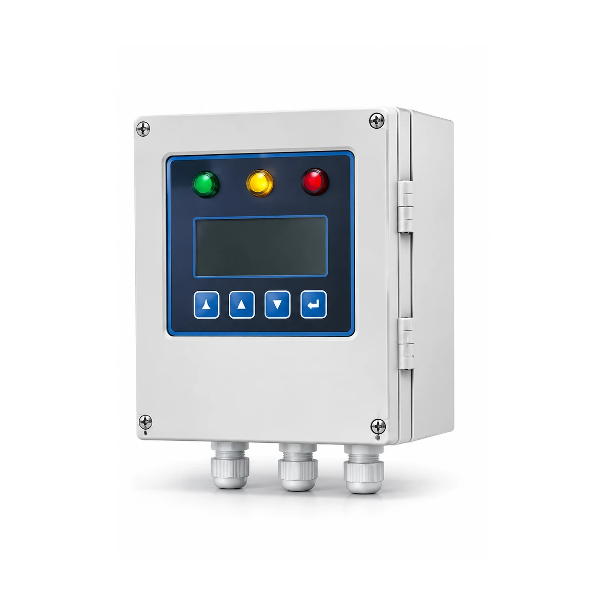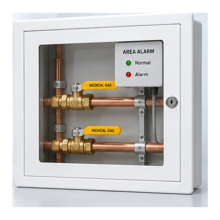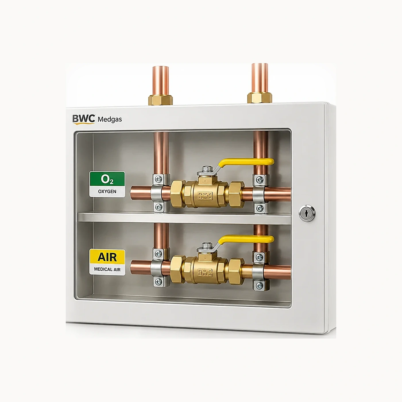

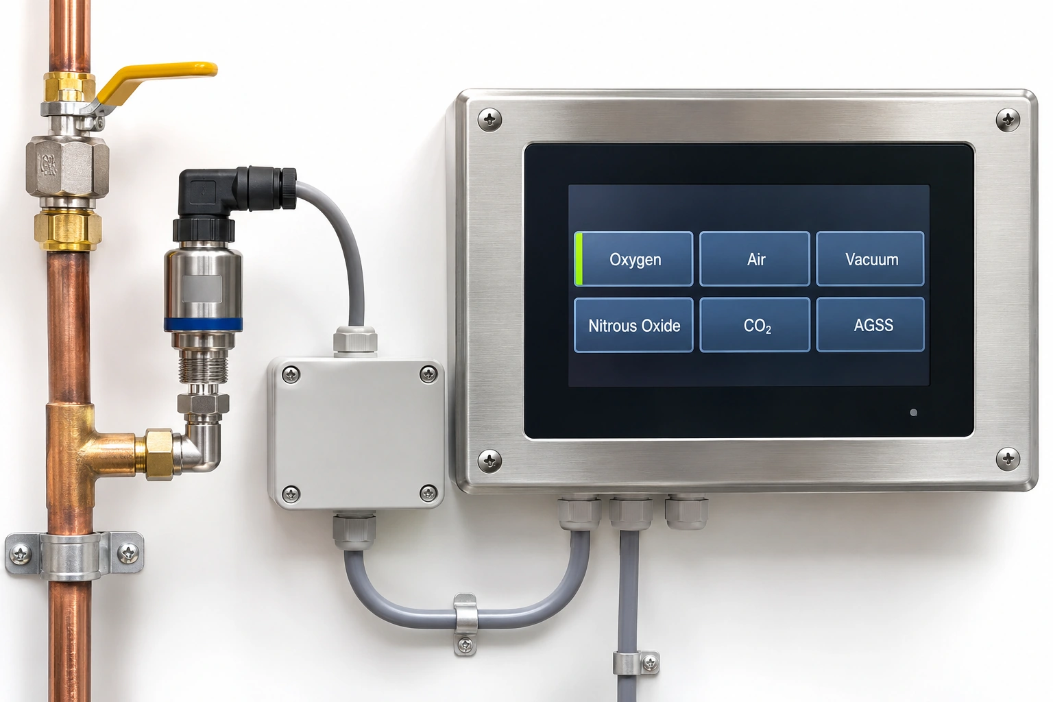
A medical gas alarm quotation may specify twelve channels and a touchscreen, yet fail to show which physical event each channel represents, who is notified or how the installed signal is proven. The useful deliverable is a cause-and-effect matrix connecting an approved medical-gas condition to its indication and response route.
This is a design coordination and verification worksheet. The hospital engineering authority defines actual operating conditions and permits; no example in this article is an alarm setpoint or an instruction to manipulate a live medical gas system.
Begin with a controlled signal inventory
Obtain current medical-gas P&IDs, source equipment descriptions, room/area valve schedules, plant alarm point lists and the hospital's operational responsibility map. Identify each monitored signal's origin, intended gas or vacuum service and clinical or engineering significance.
Keep the source or plant signals distinct from area downstream distribution signals. A local plant warning does not automatically perform the same function as a clinical area alarm. ISO 7396-1:2016 covers monitoring and alarm functions across the MGPS; its successor was still under publication as of November 2026.
Build the cause-and-effect table
| Field | What the designer must specify | Typical evidence |
|---|---|---|
| Unique point ID | Unambiguous signal identity | P&ID and I/O list |
| Origin/measurement | Exact device, location and gas service | Sensor/plant drawing |
| Defined event | Approved engineering condition, not an informal label | Functional specification |
| Indication | Visual/audible status and exact message | HMI and alarm configuration |
| Reception | Area, central or other approved panel and location | Alarm distribution drawing |
| Acknowledgment | Accepted event and user interaction behavior | Cause/effect approval |
| Fault response | Approved behavior if sensor/link/power unavailable | Failure-mode review |
| Test reference | Site witness and acceptance result ID | Commissioning record |
Do not populate the condition column with guessed pressure limits copied from a different hospital. Thresholds, delay and reset behavior need explicit competent project approval.
Separate source status from patient-area warnings
An automatic cylinder-bank changeover may be a source event, whereas a pressure abnormality downstream of a clinical zone is a different monitored condition. If both appear on a central panel, each must retain its distinct meaning, source ID and required response.
Avoid collapsing multiple different states into “oxygen alarm.” A panel can be visually simple while maintaining precise internal signal identities. Conversely, a sophisticated display with wrong mappings is not an acceptable system.
Define recipients before selecting a communication protocol
Ask where the alarm must be seen and heard, which staffed role is responsible, and whether a duplicate remote indication is required. Confirm the site's staffing and escalation pattern through the healthcare operator; a network-connected dashboard should not silently replace the designated medical-gas alarm location.
Document whether local panels, central alarm and external monitoring are independent or share equipment. The adopted national or local system standard determines required performance.
Review failure paths separately
Sensor disconnection, network communications loss, power failure and device fault can require different indication and maintenance responses. They should be separate events in the matrix rather than being hidden under a catch-all “technical fault.”
The matrix should describe how the system makes these states visible and how they will be witnessed in the approved test programme. Do not publish instructions for artificially triggering failures in an operating hospital.
Worked coordination example
An engineering drawing identifies a low-pressure signal at a ward branch, but the electrical schedule maps it to the medical air source plant instead of the ward alarm. Each vendor can meet its individual product specification while the installed receiving location remains wrong.
The project should reconcile the sensor ID, receiving panel, display message and test ID before the system is accepted. Record the revised documents and the approving parties; do not solve it by relabeling the screen alone.
Commission by signal, not only by panel
NHS Scotland SHTM 02-01 (2026) lists separate area alarm Form A14 and central alarm Form A15. Use those documents as examples of distinct evidence boundaries where applicable. The accepted project test plan should match each matrix row to actual site results, including any unresolved exceptions.
In US healthcare buildings, check the edition of NFPA 99 adopted by the authority. The latest publisher edition is not automatically the legally required edition for each project.
Procurement output for BWC
Issue one technical RFQ schedule containing I/O count and type, actual service identities, receiving locations, device power/communications requirements, manufacturer model drawings, required documentation and inspection responsibilities. Compare complete functions rather than display size.
BWC Medgas can discuss selected medical-gas area alarm panels and zone valve assemblies against this approved matrix; on-site functional verification remains with the authorized MGPS team.
Send your signal and alarm matrix to BWC Medgas.
Frequently asked questions
Does a twelve-channel alarm panel guarantee twelve correct monitored conditions?
No. Channel capacity and correct source-to-event mapping are separate requirements.
Is a BMS indication sufficient evidence of a compliant hospital alarm?
Not automatically. The project's dedicated alarm duties and accepted receiving locations must be established.