
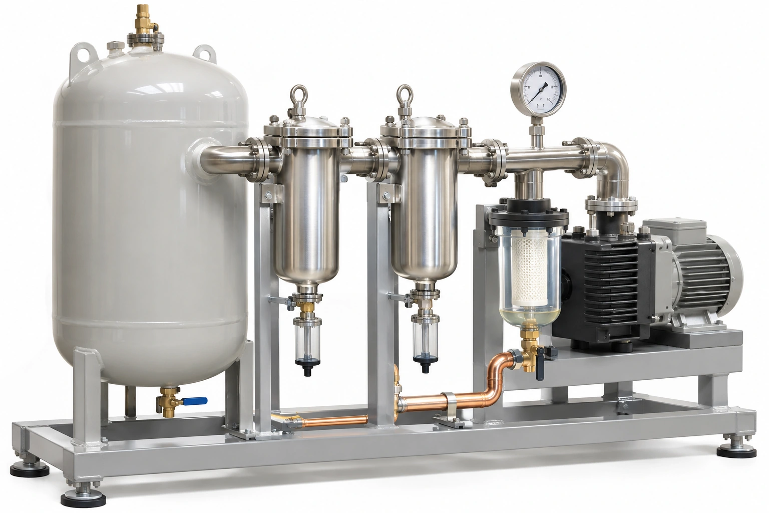
A hospital vacuum pump station may contain bacterial filters, receiver vessels, separators and protective drainage arrangements. Their purpose and maintenance requirements cannot be established simply by counting canisters or reading an advertising filtration percentage. Each item is part of the specified medical vacuum source design and needs traceable service evidence.
This guide helps procurement and facilities teams build a filter–receiver maintenance register without inventing universal bacterial removal figures or instructing staff to open contaminated equipment.
Confirm the actual system arrangement
Use the approved vacuum source P&ID to locate each filter and receiver, identify its function and determine how it relates to vacuum pumps, isolating devices, service gauges and the distribution system. The system must be designed and verified under ISO 7396-1:2016 and applicable local requirements.
Do not infer that two cylindrical filter housings are interchangeable or that a vessel can be disconnected without affecting clinical service. Their roles and permitted maintenance operations need to be specified.
What a filter datasheet must establish
Filter efficiency claims should state the test method, relevant challenge conditions, media, flow and permitted pressure difference. A generic “medical grade 99.99%” claim without model-specific evidence is incomplete.
Ask how the filter's performance and condition are monitored in the intended installation, what constitutes a replacement trigger and which handling precautions are required. The manufacturer and healthcare infection-control policy determine safe management of contaminated items.
Maintenance register
| Register item | Required detail | Evidence |
|---|---|---|
| Component ID | Unique filter housing or vessel asset tag | As-built drawing |
| Equipment position | Specific source train or connection | P&ID |
| Manufacturer and model | Exact rated size and purpose | Model datasheet |
| Performance | Stated duty, test method and flow basis | Manufacturer evidence |
| Differential condition | Approved indication or monitoring points | Instrument schedule |
| Service route | Access and planned isolation provision | Operational approval |
| Contamination controls | PPE, disposal and safe handling plan | Facility safety procedure |
| Replacement parts | Approved element/seal and part numbers | Stock register |
| Intervention | Date, personnel, observations and closure | Work order |
A record with only “filter changed” is not sufficient to establish which model or train was serviced.
Receiver vessels and drains are not mere storage
The vacuum receiver participates in the plant's control and operating behaviour. Its permissible pressure/vacuum duty, inspection regime, vessel condition, connections and any required protective/drainage arrangement must be managed separately from pump performance.
The appointed engineers should verify that condensate or accidental liquid ingress is addressed in the actual design. Do not assume a drain valve should be opened while equipment is operating; vessel maintenance belongs to qualified personnel under a controlled service permit.
Example: a supposedly equivalent element
An installer replaces a filter element using a same-diameter cartridge sourced from another supplier. The substitute lacks the approved differential pressure, filtration test and connection/seal compatibility evidence.
The buyer should reject the assumption of equivalence until the component manufacturer and project engineering authority approve the replacement. A lower unit price is not an adequate substitute for the approved system function.
Avoid mixing patient collection and central filters
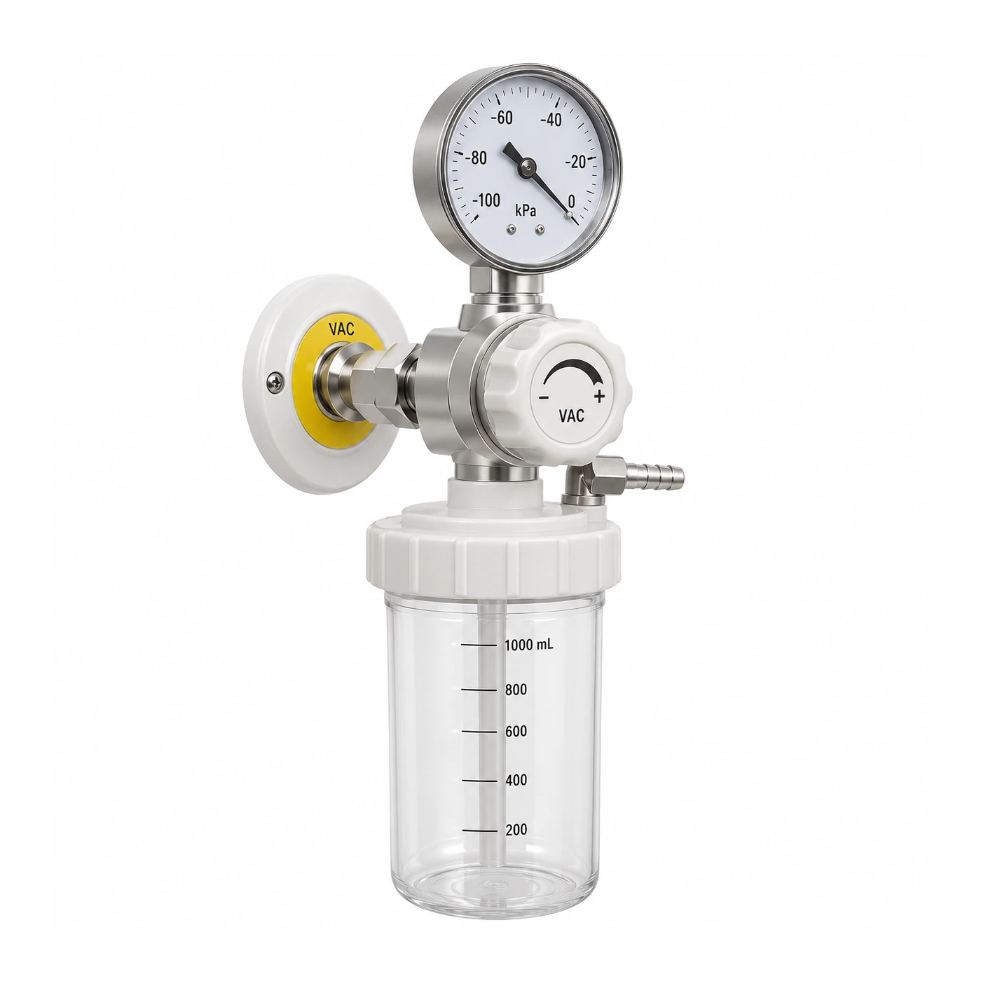
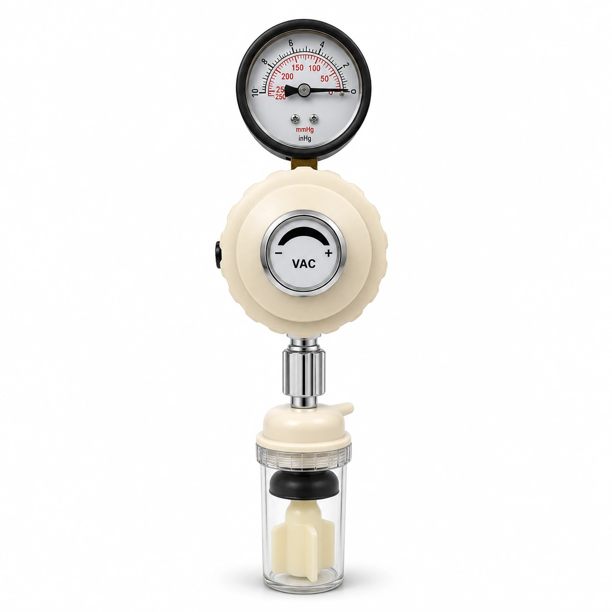
The fluid collection jar and protection accessories on a patient's suction regulator perform different tasks from bacterial filtration within the central vacuum plant. Their handling and cleaning rules also differ.
ISO 10079-4:2021 sets general requirements for medical suction equipment within its defined scope; it does not automatically certify central pipeline source filters. Device-side and plant-side evidence should be recorded separately.
Planned work and supply continuity
Any change that could affect the vacuum source needs clinical coordination and the facility's approved maintenance/permit process. The plant may have a design-provided alternate train, but this must be confirmed rather than inferred from the visual layout.
After intervention, preserve the applicable qualified functional results, updated maintenance records and handover to the operating team. Do not rely on a pump indicator alone to establish distribution-system acceptance.
Standard and operational sources
The 2026 NHS England HTM 02-01 and NHS Scotland SHTM 02-01 describe vacuum pipeline engineering and healthcare operational governance. The detailed acceptance values are determined by the approved project design and manufacturer documentation, not this overview.
BWC Medgas supplies selected vacuum suction regulators, jars and associated fittings, not the complete central vacuum station or its plant filter trains. Distinguish parts in an RFQ so that responsibility remains clear.
Discuss the exact vacuum-side component and service connection requirements with BWC Medgas.
Frequently asked questions
Is a printed filtration percentage enough to compare bacterial filters?
No. Model-specific test conditions, duty, installed position and maintenance evidence are also required.
Does a large receiver guarantee hospital vacuum continuity?
No. Complete controls, pumping capability, source availability and distribution performance determine continuity.