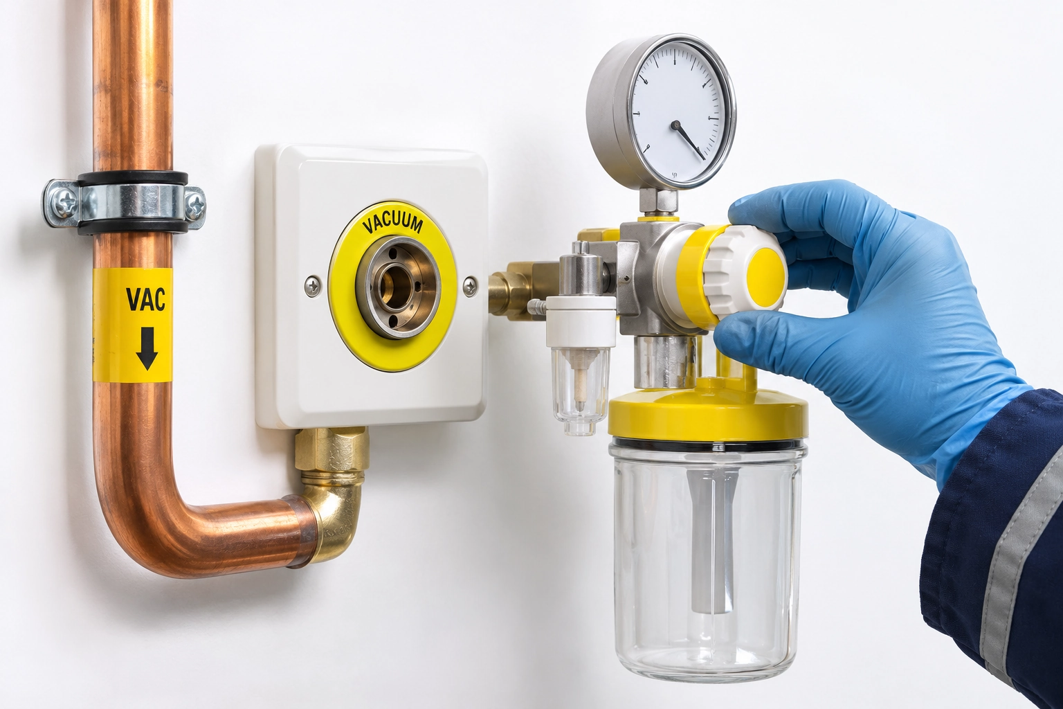
A hospital's central vacuum source may display a satisfactory operating condition while a remote ward reports poor suction at its equipment connection. The discrepancy may concern a patient-side regulator, terminal interface, branch pressure loss or the source plant's actual available duty. The issue cannot be resolved by reading the plant gauge alone.
A location-traceable terminal performance record makes the physical boundaries visible to procurement, commissioning and maintenance teams without asking staff to interrupt suction to test it.
Separate plant, distribution and point-of-use equipment
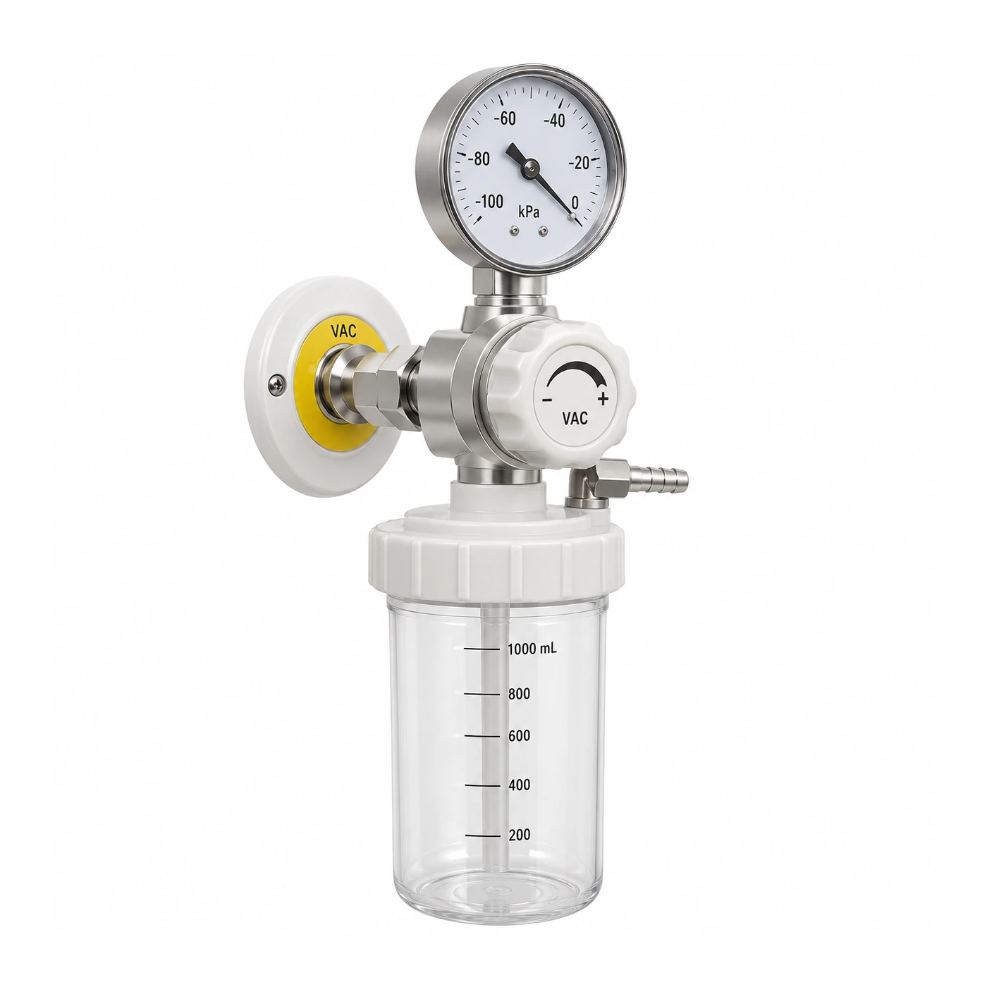
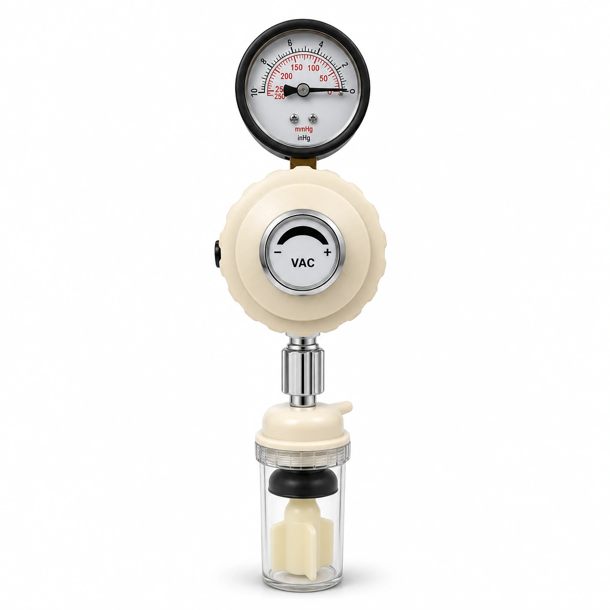
The ISO 7396-1:2016 system includes medical vacuum sources, pipelines, terminals and their verification. ISO 10079-3:2022 governs defined suction devices powered from such vacuum or positive-pressure sources. A medical vacuum terminal is not a complete suction regulator/jar assembly.
Each potentially relevant observation should be associated with its exact installed source train, branch/zone and terminal position. A number without location cannot establish which equipment is affected.
Build a branch and terminal evidence map
| Point | Required information | Evidence |
|---|---|---|
| Terminal ID | Exact room, bed position and outlet identifier | As-built plan |
| Gas service | Correct medical vacuum identity | Terminal and pipeline marking |
| Served branch | Network path and isolation boundary | Approved P&ID |
| Demand case | Design-required operating/flow condition | Design calculation |
| Source state | Relevant pumps, reserve, alarms at the time | Engineering event log |
| Measurement | Gauge/absolute basis and actual testing location | Approved test sheet |
| Connected device | Suction regulator, jar and compatible interface | Biomedical asset record |
| Acceptance | Approved installed vacuum delivery test and witness | Commissioning dossier |
This register helps avoid the assumption that two nearby terminals have identical network paths.
Understand pressure loss without inventing values
Any flow through pipework is associated with resistance; changes in route length, diameter, branches and installed restrictions can affect the delivered vacuum conditions. The approved design calculation should cover the required terminal duty and diversified system load.
Do not substitute one rule of thumb for detailed sizing or use an unrelated hospital's accepted test result as a new project's required pressure.
Distinguish a device fault from a pipeline fault
A suction regulator or collection assembly may have a blocked filter, damaged connection or other equipment problem. A correctly functioning regulator cannot compensate for a deficient source, but a strong central plant also cannot prove the regulator itself is healthy.
The hospital's qualified team should use approved methods to separate the two. Never disconnect patient equipment or test by opening vacuum piping on an occupied clinical area without formal permits.
Example: one ward, repeated reports
Several rooms report weak suction, but nearby intensive-care beds remain unaffected. Before ordering more pumps, review the affected terminal IDs, branch drawing, source event history, equipment model and the relevant performance evidence.
The findings may show a common downstream element or an equipment-specific issue. The record guides investigation; it does not pre-judge the root cause.
Commissioning and later extensions
The 2026 NHS HTM 02-01 and Scottish SHTM 02-01 provide the approved management context, with separate pipework, vacuum plant and terminal/area evidence requirements.
Each extension should produce revised as-built routes, source loading assessment, tested zone boundaries and recorded results for newly affected terminals. Confirm that the maintenance/clinical teams know which installed area each document covers.
A replacement procurement note
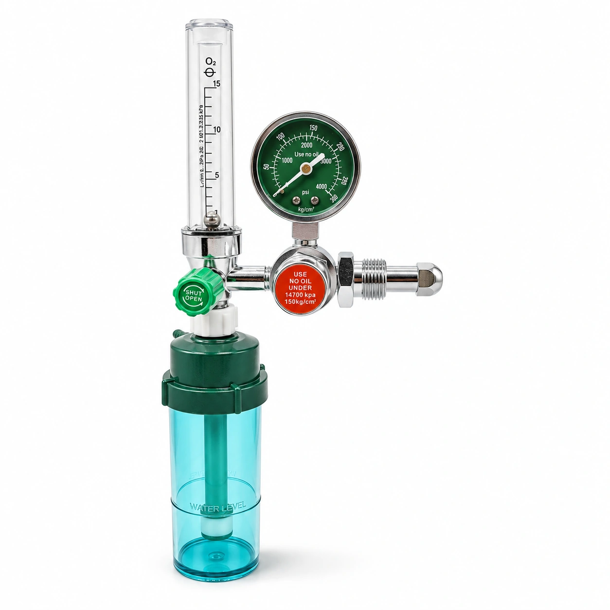
If terminals or suction device connectors are changed, specify exact gas-specific interface family and approved equipment connection. Avoid accepting a product on shape similarity alone. New interface components can be mechanically incompatible even if the catalogues use the same word “vacuum.”
Maintain an asset map linking component model and revision to the tested terminal location.
Operational follow-up and BWC
Collect defect history, repeat events, changed zone layouts, maintenance status and qualified retest evidence. This supports a risk-based engineering response while leaving patient care decisions with the healthcare team.
BWC Medgas offers selected vacuum regulators and associated gauges and zone-valve assemblies against approved connection and installed-interface specifications. It does not perform the hospital's live pipeline verification.
Send a terminal/interface schedule for BWC component supply.
Frequently asked questions
Does a normal plant display guarantee usable suction at every bedside terminal?
No. Distribution and connected equipment require their own accepted verification.
Can a vacuum regulator with a similar connector automatically replace an old model?
No. Model, gas-specificity and manufacturer compatibility must be confirmed.