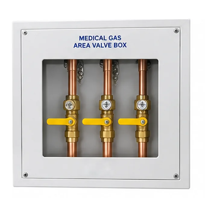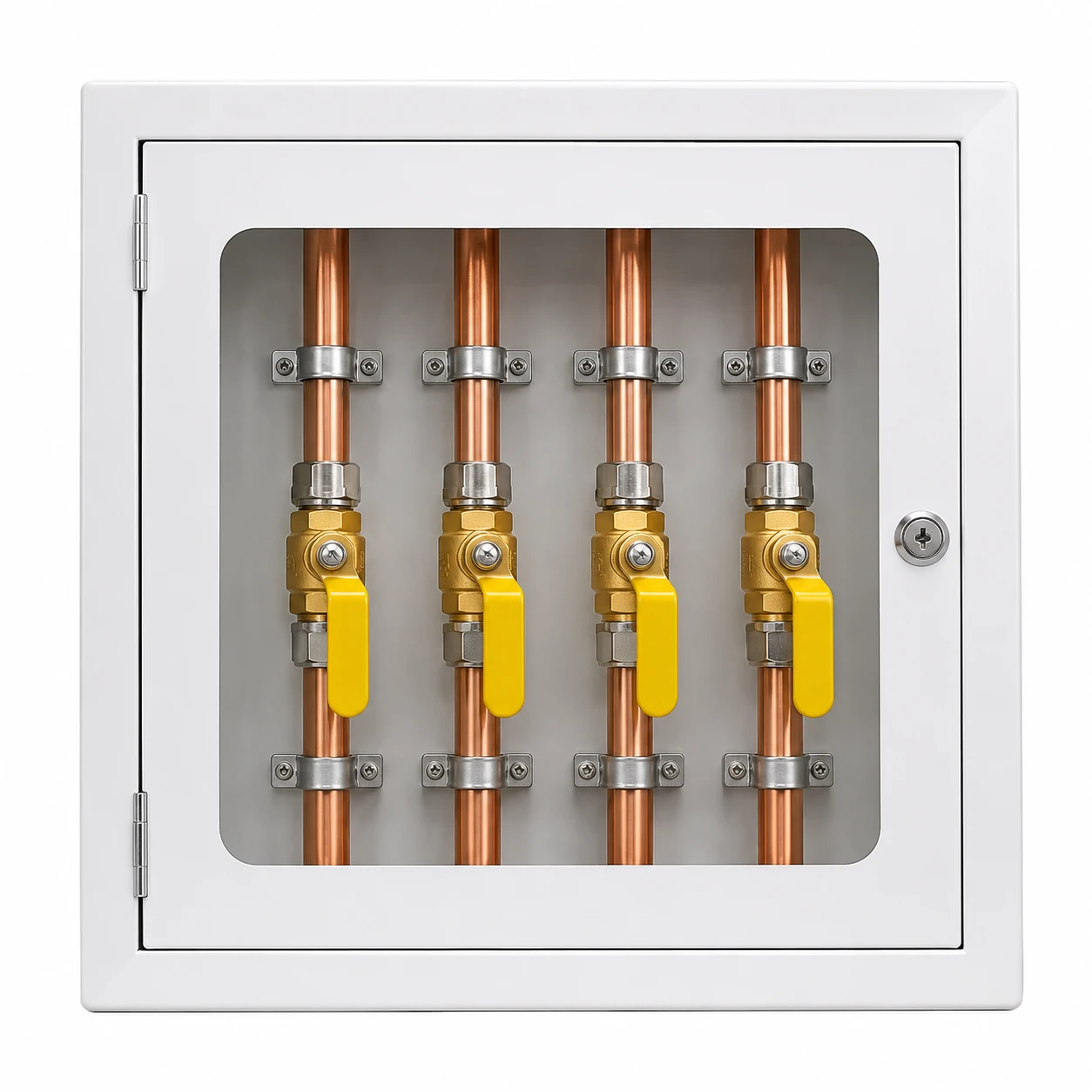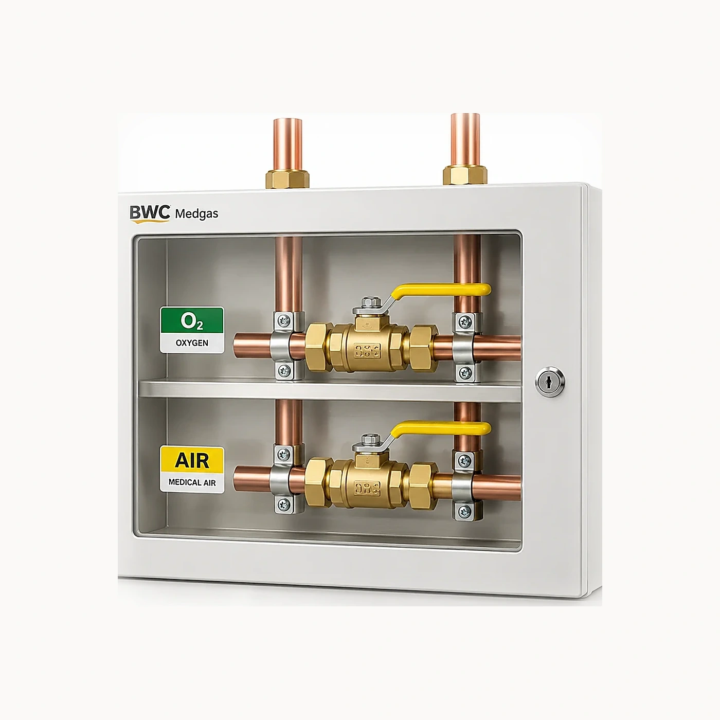

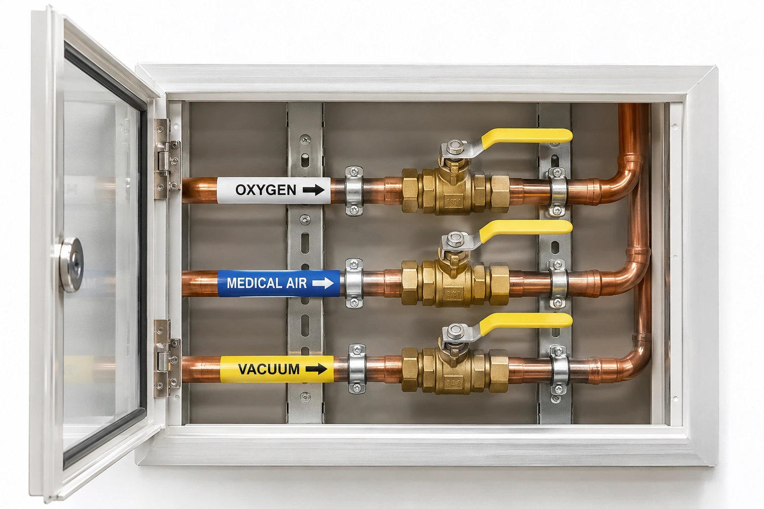
An area valve service unit (AVSU) can be physically close to a ward and still serve a different group of rooms from those suggested by the corridor signage. In an emergency or during planned maintenance, knowing exactly what is downstream matters more than the number of valves visible behind a panel.
A room-to-valve map is a controlled engineering record linking each gas or vacuum service, the actual network, its isolation boundary and the clinical spaces affected. The purpose here is to prepare a traceable design/operations document—not to instruct untrained personnel to close valves or disrupt a live supply.
Start with a verified source and network diagram
Collect current approved distribution P&IDs, room and terminal schedules, valve locations, riser/branch plans and relevant renovation history. Mark which drawings have been verified against installed conditions by the competent site team. Older drawings may be inaccurate after hospital extensions.
Define separately the service and the isolation device: oxygen, medical air, vacuum and other specified gases may traverse similar corridors but need their own verified connections and service identity. A box labelled “three gases” does not necessarily mean that all three serve exactly the same rooms.
NHS HTM 02-01 (2026) and the published ISO 7396-1:2016 cover medical-gas pipeline distribution and system documentation. The national code chosen for the project still controls the approved arrangement.
Make the zone register service-specific
Use a row per valve per service. The same room may be covered by different service boundaries.
| Data element | Example of what to record | Responsible evidence |
|---|---|---|
| Valve asset ID | Hospital-issued unique identifier | Asset register |
| Medical gas service | Oxygen / medical air / vacuum, separately | Verified MGPS diagram |
| Installation location | Building, level, door/corridor reference | Site-approved plan |
| Served boundary | Exact ward, rooms and included branches | Competent survey and verification |
| Upstream relationship | Parent valve, source or branch reference | Controlled P&ID |
| Nearby terminals | Terminal schedule IDs | Room-by-room crosscheck |
| Alarm boundary | Monitoring and area alarm map | Alarm engineering dossier |
| Clinical owner | Relevant department and escalation role | Hospital operational policy |
| Verification status | Proven / provisional / unresolved | Authorized reviewer |
Do not mark a row “confirmed” merely because the faceplate text matches the drawing.
Review overlap and gaps
Ask whether a valve affects more than the intended department, whether any clinical room is unaccounted for, and whether extensions share an upstream branch that crosses planned clinical zones. Mark any contradictory information and assign a competent verifier to resolve it.
A useful check is to join the room schedule and valve map by the installed gas terminal IDs. For every terminal, the hospital should be able to identify which approved isolation arrangement applies. This is a document reconciliation task—not a live valve operation.
Example: two wards behind one corridor box
A building drawing labels a valve box “Ward A,” but a later branch to Ward B was added upstream of the recorded boundary. Procurement plans to replace the Ward A box in an occupied hospital.
The review should mark the actual served-room boundary as unresolved and require a controlled site survey and clinical impact review before any work is authorized. It must not assume Ward B is unaffected because the box label still says “Ward A.”
Distinguish AVSUs, line valves and other devices
A UK AVSU generally supports defined clinical area isolation and has distinct access/operational requirements from a line valve assembly (LVA). A US zone valve box is evaluated under the facility's adopted edition of NFPA 99. Do not convert one standard's part number into the other without checking the complete functional and regulatory requirement.
The published SHTM 02-01 (2026) includes separate Form A4 for AVSU zoning/closure/NIST checks and Form A5 for line valves. Those are useful evidence categories for a zone register.
Use the map to improve tenders
For each valve or box, define the actual services, approved size/connection schedule, number of individual valve assemblies, monitoring interfaces, enclosure/access requirements, labels and test evidence. An unexplained price for a “5-gas box” cannot establish whether the five specified valve functions are present.
Request exact component drawings and model configuration. Where a supplier proposes a smaller enclosure, review access, installation, labeling and testing implications with the project designer.
Hand over the map as a living asset record
At completion, link the final valve IDs, room schedule, as-installed drawings, alarm map, commissioning tests and approved operating instructions. Keep a revision/date and a named owner for future changes. A temporary hospital corridor label should never be the sole source of the valve's served-area information.
BWC Medgas can quote specified area valve boxes and line valves against a verified room-to-valve matrix; it does not make the hospital's clinical isolation decisions.
Send an approved valve-zone and component schedule to BWC Medgas.
Frequently asked questions
Does one physical box always isolate one complete ward?
No. The actual approved service-by-service pipework topology determines the affected area.
Is the valve name plate sufficient to confirm the isolation boundary?
No. Verify against current diagrams, location information and designated site evidence.