
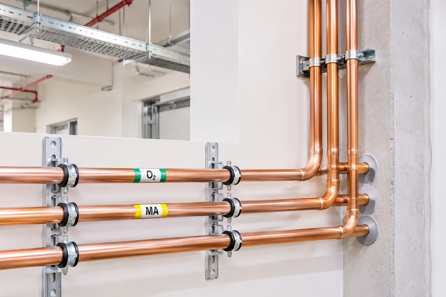
A medical-gas copper route can appear to fit perfectly on a schematic while being impossible to install in a real ceiling. It may cross a structural opening that was never approved, clash with other MEP services or pass through a fire-rated compartment without a defined penetration detail. Moving the tube “a little to the left” on site can invalidate drawings and acceptance evidence.
A pipework coordination and access register helps the design, building and MGPS teams resolve these problems before construction. Actual support design, fire-stopping and permitted routing depend on the adopted code, materials and the project engineering approval.
Start with system identification and route ownership
Every medical gas and vacuum service should have an approved drawing identifier and route. Record the gas-service name, source and served zones, riser/branch identifiers and the applicable engineering design revision. Do not use a copper-colored line in a BIM model as proof that it represents the intended gas.
Identify who owns each interface: MGPS designer, architectural coordinator, structural engineer, fire consultant, building-services trades and the healthcare estate operator. A clash ticket without a decision owner is an unresolved risk.
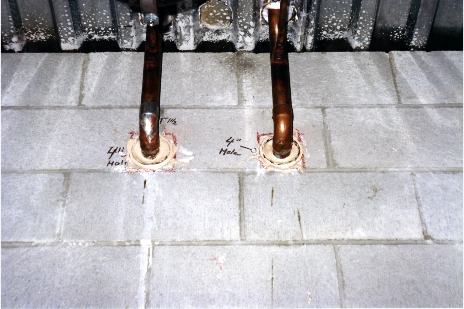
Look at construction zones, not just the pipes
Use one coordination row for each critical segment: service riser, corridor main, branch to clinical room, bedhead connection and the connection to a source or terminal package. Link the row to the current approved model or plan and the relevant construction phase.
| Review point | Question to answer | Required evidence |
|---|---|---|
| Corridor route | Is the final route buildable with other services? | Coordinated drawing or approved model |
| Support arrangement | Has the specified service/support design been reviewed? | Approved support detail and inspection |
| Riser entry | Are openings and access arrangements accepted? | Structural and MEP coordination record |
| Fire compartment | Is an appropriate penetration/firestopping detail approved? | Fire strategy and completion evidence |
| Service access | Can specified inspection and maintenance be performed? | Access review with estates |
| Zone interface | Do service branches match the approved served areas? | Zone diagram and terminal schedule |
| Identification | Is the required gas labeling/marking defined? | Approved marking schedule |
A combined project drawing can show most of these relationships, but the register makes their decisions visible.
Fire compartments and penetrations are distinct disciplines
Do not assume the MGPS installer can choose any sealing material at a fire-rated wall. Penetration systems must be accepted by the relevant fire-safety design/inspection process, considering the actual wall/floor, service material and tested/approved system.
The pipework contractor should provide the needed geometry and installation sequence; the fire specialist should define the permitted barrier detail. The handover record should link the installed penetration to its applicable specification and completed inspection.
A product labeled “fire sealant” does not by itself certify every penetration arrangement.
Supports need approved spacing and access assumptions
A source-free “every copper pipe needs a support at X metres” table is not a sound public medical-gas design rule. Tube size/condition, orientation, load, environment and adopted installation requirements affect the decision.
Use the design-approved support schedules, material interfaces and manufacturer requirements. Review movement, other service conflicts, accessibility, identification and potential damage during construction. Ensure a support does not force an inappropriate connection or make the route impossible to inspect as specified.
A support quantity in the bill of materials should be derived from the approved plan, not guessed after the tube order.
Coordinate bedheads and terminal connection points
A building designer may move a bedhead or pendant after the corridor route is approved. That change can affect branch routing, terminal interface and future access. The MGPS engineer should compare the clinical room matrix, terminal schedule and final physical arrangement.
Where a branch meets a third-party bedhead, define the exact supplied connection, the owner of the mating component, inspection duties and responsibility for the installed-system verification.
Use clash resolutions that survive construction
A good issue record contains: affected service, segment ID, drawing/model view, actual conflict, clinical/operational implication, responsible designer, revised solution, approval status and date. Resolve clashes before the field order where possible.
For example, a proposed duct route crosses the medical-gas riser opening. The alternatives must be reviewed for geometry, fire protection, structure, hydraulic consequence and service continuity. A note reading “adjust on site” should not bypass this review.
The as-installed control point
At the end of construction reconcile actual routes, penetrations, branch/zone labels and any authorized deviations with the as-built drawings. The final dossier should support the hospital's future maintenance and safe work planning.
ISO 7396-1 defines MGPS system-level scope. HTM 02-01 (2026) and SHTM 02-01 (2026) address installation and verification in UK healthcare estates. Australian projects may reference AS 2896:2021, subject to local adoption and contract.
BWC Medgas pipework package
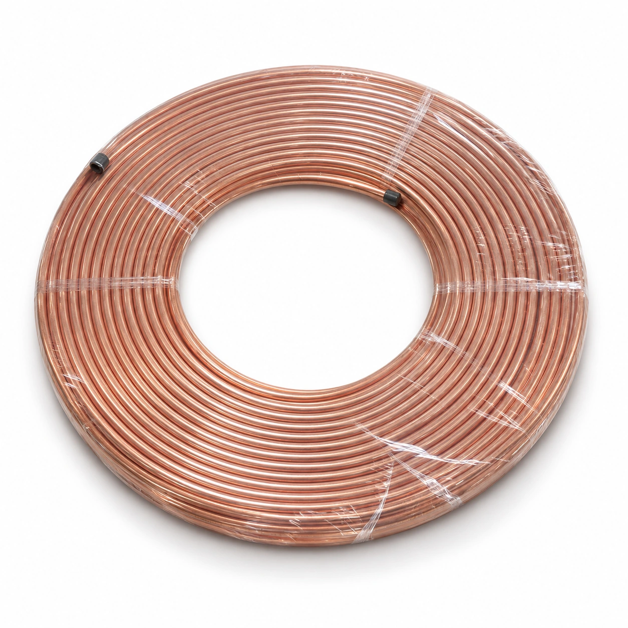
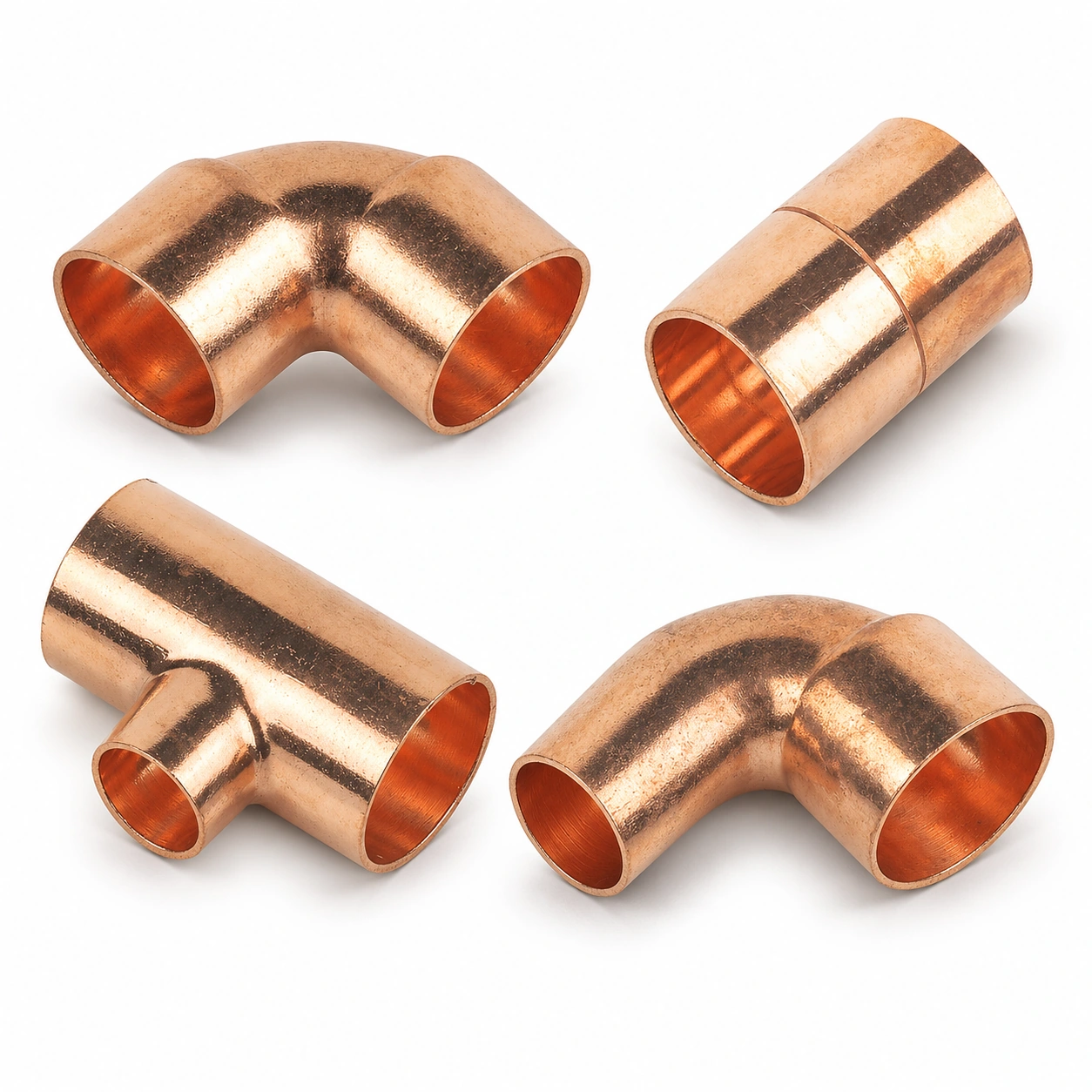
BWC Medgas can quote the specified medical-gas copper tube, fittings and selected line valves. Correct engineering routes, support arrangements and building coordination remain project design obligations.
Send an approved MEP pipework schedule to BWC Medgas.
Frequently asked questions
Can an on-site pipe reroute be accepted without changing drawings?
Not by assumption. The change should be reviewed and recorded in the project's approved design/as-built process.
Does supplying a firestop material resolve a penetration approval?
No. The actual approved penetration assembly and completion evidence matter.