
A medical-gas pipeline can have all the specified copper tubes installed correctly and still be unable to satisfy the approved performance at the most demanding terminal. Pipe size depends on the actual service, demand and network, not merely on how many outlets appear on a floor plan.
A high-value design review makes flow and pressure assumptions transparent on a segment-by-segment worksheet. Only a qualified designer should determine actual pipe diameters and verify the source, valves and terminal performance in the applicable code context. This is a review and procurement-control method, not a universal pipe-sizing table.
Start with the approved clinical duty
Have the engineering and clinical teams define the operating cases and required performance for oxygen, medical air, vacuum and any other service separately. An outlet count does not equal simultaneous flow, and a given gas service must not inherit design values from another service.
For each approved scenario record which equipment is in use, the associated demand basis, any justified diversity or simultaneity approach, source operating condition and critical destination.
Attach the calculation revision and the party approving these assumptions. If a ward changes clinical function, the network model should be reviewed rather than silently adding terminal symbols.
Divide the path into engineering segments
A useful segment register contains:
| Segment field | Why it matters |
|---|---|
| Segment ID, drawing revision and gas | Connects analysis to the approved route |
| Upstream and downstream nodes | Establishes network connectivity |
| Tube designation and internal dimensions | Connects material choice to the model |
| Length and relevant geometry | Defines path contribution |
| Approved segment design flow | Prevents arbitrary demand copying |
| Applicable fittings/valves | Captures design-approved local losses |
| Relevant pressure/temperature assumptions | Maintains consistent calculation basis |
| Resulting segment loss and reference | Makes the model auditable |
The designer chooses the governing calculation method. A spreadsheet copied from a water-plumbing project is not automatically valid for compressible gas or medical vacuum.
Reconcile geometric length and effective losses
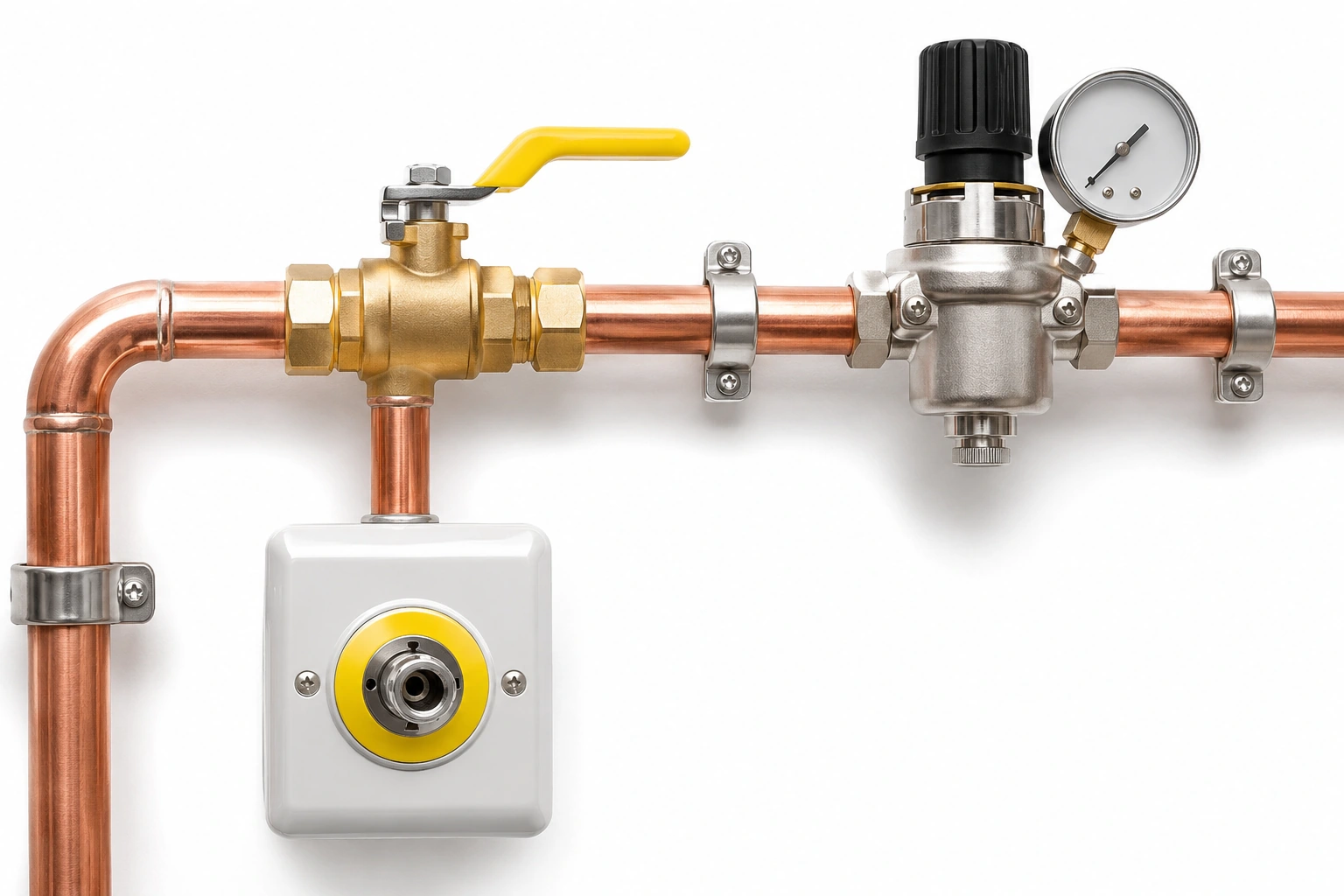
A straight copper run is only part of the path. Changes in direction, connectors, regulators and other components may create additional losses that depend on the approved design method.
The calculation should explain how fitting/valve loss data were obtained and whether the chosen method treats their effect as equivalent length or another supported approach. Do not invent coefficients merely to make the spreadsheet produce a convenient diameter.
When supplier data are required for a component, quote the exact model rather than a generic catalogue photo.
Check the critical path, not just total quantity
A common review scenario is that the nearest outlet meets the intended duty, while a remote high-demand clinical area has an inadequate pressure margin. The design authority should identify the critical terminal under each relevant demand case and examine the combined path from source to that destination.
The route with the longest geometric length is not necessarily the controlling case; flow, components, branches and source conditions can alter the result.
The same principle applies to vacuum performance with the appropriate technical method and criteria.
Use an arithmetic illustration without prescribing a design
Suppose an already-approved engineering calculation attributes 6 kPa of loss to one segment and 4 kPa to the next, and 3 kPa to a specified downstream component. The illustrative subtotal is 6 + 4 + 3 = 13 kPa.
This is merely addition of already-determined results. It is not a permitted loss, an actual design value, a pressure setting or proof that a selected pipe is compliant. The engineer must evaluate the complete system against project-specific requirements.
Plan a change-control trigger
Require a design review if any of these change: clinical function, terminal demand assumptions, source arrangement, tube internal dimensions, routing, significant fitting/valve configuration, service zone or manufacturer component duty.
Keep the old and new model revisions, the affected segment IDs and the decision record. This prevents a value-engineering substitution from eroding the intended performance without a formal evaluation.
Procurement decisions linked to the model
The buyer should receive an approved material schedule with standard/edition, tube diameter and wall requirement, form/temper, quantity and exact associated fittings. Materials cannot be ordered accurately from a demand worksheet alone.
If a supplier proposes a different standard or wall thickness, the designer must assess dimensional and hydraulic implications before issuing the purchase order.
Documentation at completion
Retain the calculation basis, revised route/segment schedule, accepted component data, deviations, construction records and relevant site verification evidence. A successful factory demonstration for one fitting is not a substitute for system-level pressure/performance verification.
Relevant frameworks include ISO 7396-1:2016, 2026 NHS HTM 02-01 and the adopted local code. Australia uses AS 2896:2021 for the specified non-flammable medical-gas installation and testing scope; the governing project and authority determine applicability.
BWC Medgas product interfaces
Once the designer approves quantities and sizes, BWC can quote specified medical-gas copper tubes, elbows/tees and compatible project components. The supplier's price must not be presented as a replacement for the project engineering calculation.
Send the approved segment-based material schedule to BWC Medgas.
Frequently asked questions
Is a “typical oxygen pipe diameter” safe for every ward?
No. The complete network and accepted demand/performance criteria determine sizing.
Does a pressure-loss worksheet replace installed-system verification?
No. Calculations and commissioning evidence answer different questions.