
Medical gas projects are often delayed because two technically competent teams work from drawings that describe different versions of the same installation. The architect moves a clinical wall, the HVAC engineer relocates a riser, or a bedhead layout is revised after valve zoning has already been approved.
A controlled MGPS drawing register is the practical defense against this mismatch. It does not merely list file names: it connects each drawing to its purpose, revision, approval state and related schedules.
What drawing families should the project consider?
A typical project may require these coordinated views, adjusted to the approved scope:
- System schematic / P&ID: source interfaces, main distribution, isolation devices, pressure-control arrangements and monitoring points at the system level.
- Riser or vertical distribution diagram: where services move between floors, with clearly identified vertical routes and isolation boundaries.
- Floor coordination drawings: medical gas routes, pipe sizes as approved by the designer, other MEP interfaces and service access.
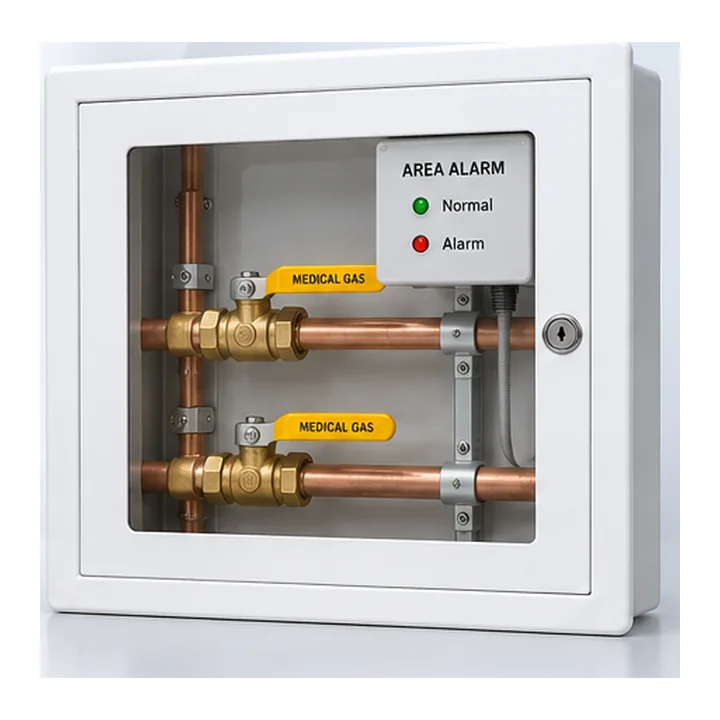
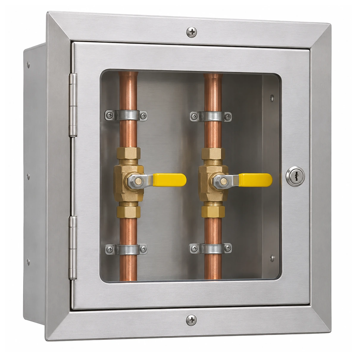
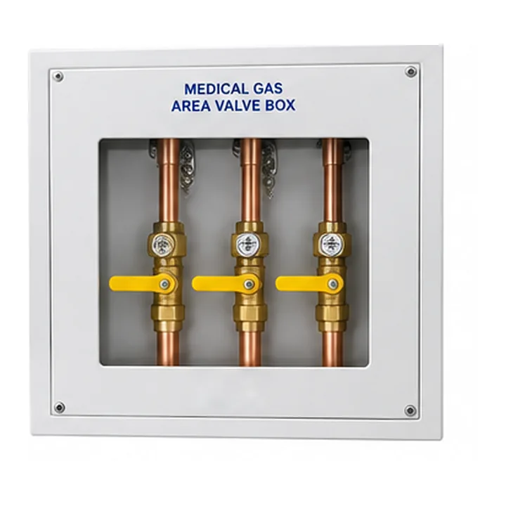
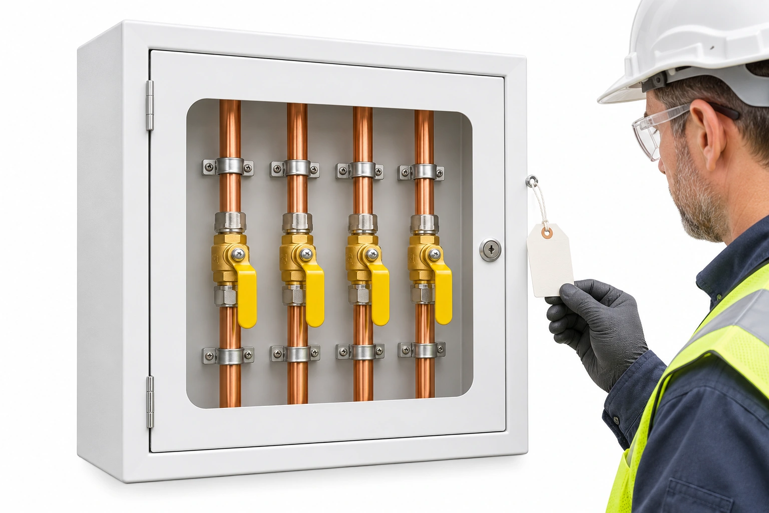
- Valve-zone plans: zones controlled by each AVSU or valve group, the room IDs served and relevant alarm interfaces.
- Clinical terminal location plans: exact gas services and terminal positions at bedheads, walls or pendants.
- Plant/source interface details: mechanical and electrical handoff points, component assemblies and agreed boundaries.
- Typical installation details: service identification, access, support and relevant installation requirements.
- As-installed record drawings: the verified configuration handed over to the operator, not simply the last construction issue.
No single drawing can reliably replace all of these information sets.
Construct the register as an actionable dataset
For each entry record the document ID, description, service, building/level, revision, issue date, author, approval stage, superseded revision, connected schedule and the person responsible for coordination. Status labels such as for review, for construction and as-installed should have defined meanings.
An illustrative entry could be:
- MG-PID-001 — oxygen distribution schematic — revision D — approved for coordinated construction.
- MG-ZONE-205 — level 2 isolation boundaries — revision C — clinical review pending.
- MG-TU-205 — level 2 terminal locations — revision E — coordinated with bedhead supplier.
- MG-IF-007 — manifold connection details — revision B — manufacturer drawing review pending.
These document IDs are examples. Do not use them as a substitute for the project’s own controlled numbering scheme.
Cross-check the drawings in both directions
Read from the room outward: a terminal on the room plan should correspond to a terminal schedule, a service branch, an isolation zone and the appropriate source architecture.
Then read from the source inward: a system branch shown on a schematic should have a route on the coordination drawings and a clear connection to the served clinical areas. This two-way review can reveal omitted zones, mislabeled services and drawings that use outdated room IDs.
Use an issues register to record each conflict, owner, decision deadline, revised drawing and closure evidence.
Add an explicit review of renovation boundaries
For extensions and modifications, mark the existing, to-be-removed, retained and new elements. Record where survey evidence is incomplete. Use verified existing-system drawings and inspections; never assume the original as-built exactly reflects the current installed network.
Show the connection boundary, likely clinical impact, required approvals and the planned verification strategy on controlled project records. The final approach is determined by the hospital’s responsible parties and the applicable safety procedures.
How the document set supports commissioning
NHS Scotland’s updated SHTM 02-01 page lists test forms addressing terminal-unit schedules, valve-zone tests, alarms, supply plants, design review and as-installed information. These show why drawings are not merely commercial artifacts: they help identify what must be checked and recorded.
Similarly, NFPA’s 2027 edition highlights a stronger emphasis on medical gas system diagrams. The contract should specify which drawing evidence and identification requirements govern the site; local adoption and the authority having jurisdiction matter.
Handover deliverables worth checking
Before the contractor closes the package, compare the drawing register with the actual testing and change records. Ensure final documents show the installed zone boundaries and correct service names. Include the drawing index in the handover dossier so maintenance personnel do not need to reconstruct the system from purchase invoices.
Where documents disagree, treat it as an unresolved handover item requiring responsible review, rather than choosing the latest PDF by file modification date.
BWC Medgas component reference
A drawing register makes component requests clearer. Include relevant drawings when enquiring about gas outlets, AVSUs and zone valve boxes, copper tube and fittings or manifold-related parts, and keep the full construction and testing scope with the appointed project parties.
Discuss drawing-based component specifications with BWC Medgas.
Frequently asked questions
Is the P&ID sufficient for purchasing outlets?
Usually not. A terminal schedule and gas-specific interface drawing are also needed to identify the exact equipment.
Is a construction drawing automatically an as-built drawing?
No. As-installed information should be updated and checked against the completed system.