
A medical gas project may be divided among a source-equipment contractor, an MGPS installer, a bedhead or pendant supplier, a controls specialist and the hospital’s own estates team. The result can be a dangerous contractual gap: every supplier believes that someone else provides a connector, alarm interface, final test or handover document.
A system boundary register identifies the physical and contractual handoff points before pricing starts. It is particularly valuable when the hospital buys components directly or divides procurement across work packages.
Draw the functional chain first
Begin with the approved project architecture rather than product pictures. A simplified functional chain is:
- Source and storage — for example approved cylinder manifolds, liquid oxygen infrastructure or an on-site source selected by the project.
- Distribution — piping, isolation, supports, markings and pressure/control arrangements in the approved design.
- Monitoring and alarms — sensing locations, alarm types, power and communications interfaces.
- Area isolation — valves and AVSUs controlling defined clinical zones.
- Terminal unit — the gas-specific point of connection in a room or bedhead.
- Point-of-use equipment — hoses, flow-control devices or clinical equipment chosen for the intended medical application.
This chain identifies interfaces; it is not a substitute for the detailed design or a direction to connect equipment in a particular manner.
Record one owner and one acceptance deliverable per interface
Create an interface register with a unique ID. For each boundary, define the upstream package, downstream package, owner of design coordination, owner of supply, installation responsibility, verification responsibility and required evidence.
For example:
- IF-01: manifold outlet to downstream distribution. Confirm the approved service, connection arrangement and who supplies the mating component.
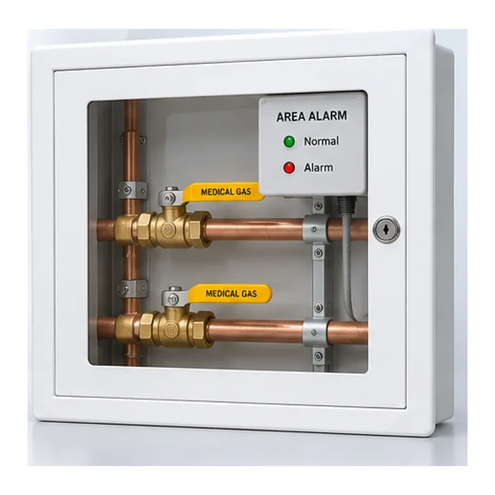
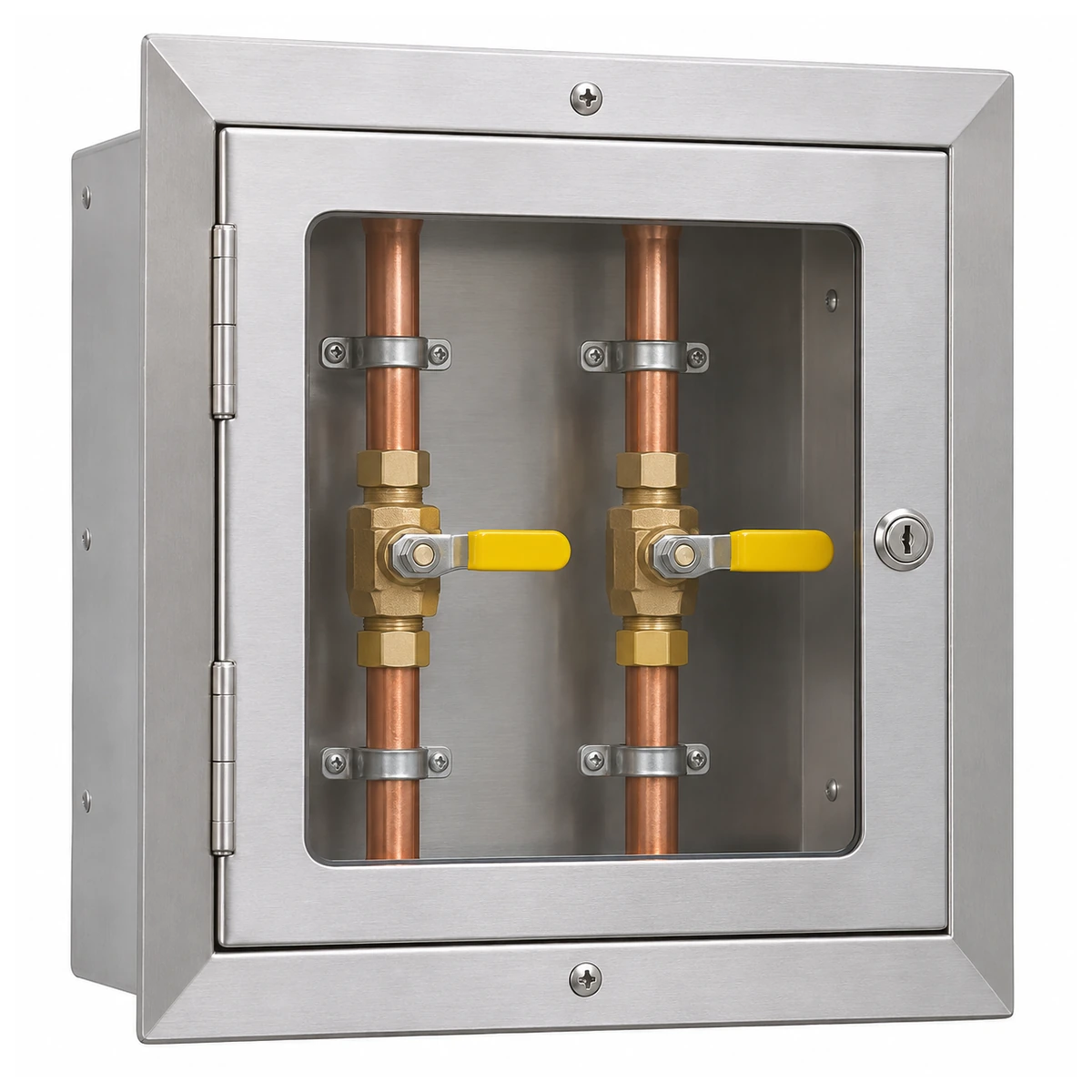
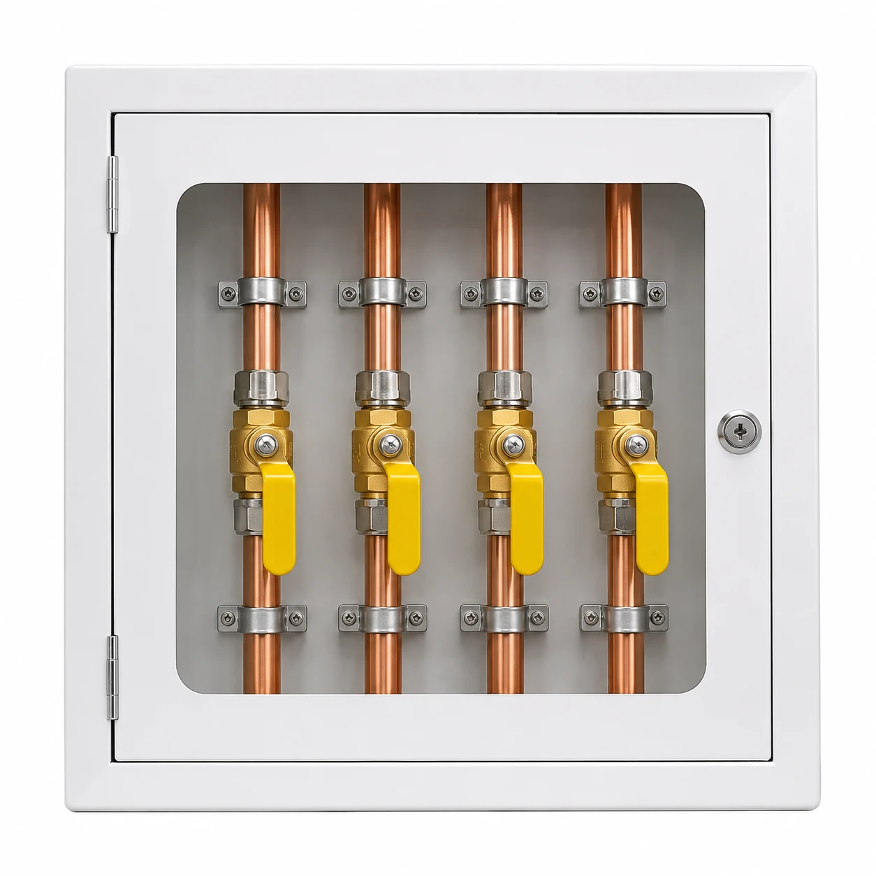
- IF-02: distribution to zone valve box. Identify assembly scope, pipework connections, zone label, accessibility and test boundary.
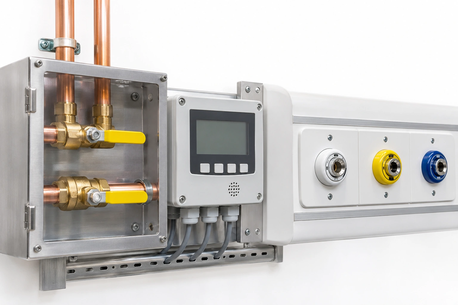
- IF-03: valve/pressure signals to alarm system. Record signal source, input type, functional responsibility and test document.
- IF-04: pipeline branch to bedhead terminal. Define terminal family, mounting hardware, rear connection and which contractor seals and verifies the work.
- IF-05: terminal to user device. Record the specified gas-specific connector family and the product documentation required.
The words “complete medical gas installation” do not resolve these details.
Distinguish physical boundaries from commercial boundaries
A product supply quote can be valid even if the supplier does not install it. Problems arise when the bill of materials silently treats a component as a complete subsystem.
For each proposed purchase, ask: is the quoted item a loose part, a factory-assembled module, or a fully installed and commissioned subsystem? Do the drawings show accessories and mating parts outside the supplier’s package? Will the source contractor supply only the plant or also some downstream manifolds and alarm interfaces?
The answer belongs in the contract scope schedule and should be consistent across drawings, procurement schedules and testing plans.
Typical gaps discovered during interface review
- A valve box is quoted without the specified gas-service identification or enclosure arrangement.
- A terminal is ordered for the wrong national mating connection.
- A bedhead contractor assumes terminal units are supplied by the pipeline contractor.
- A monitoring vendor receives contact points but not the agreed signal/alarm logic.
- The installer and source contractor each exclude verification at their connection boundary.
- A refurbishment package omits the legacy interface drawing needed for compatibility.
Each gap has a practical remedy: a documented owner, a precise drawing reference and an agreed acceptance record.
Use scope reviews at three project stages
Concept: confirm which subsystems are in scope, which parties are appointed and which interfaces are high risk.
Before order placement: confirm product quantities, the exact connection geometry, inclusion/exclusion lists, deliverable drawings and test responsibilities.
Before clinical use: reconcile as-installed interfaces, outstanding defects, verification records, operational ownership and the site handover package.
The register should be version-controlled because a new contractor or equipment change can shift interface responsibility.
What BWC Medgas can support
BWC Medgas supplies component categories such as gas-specific outlets, isolation valves and zone valve boxes, manifold hardware, alarms and installation accessories. It is important not to confuse these component offerings with complete oxygen/air/vacuum plant packages.
For a component request, include the interface register lines that apply to the offered equipment, with an approved connection drawing and explicit included accessories. Send your MGPS interface schedule to BWC Medgas.
Frequently asked questions
Is the system boundary the same as the contract boundary?
Not necessarily. The physical boundary exists at the equipment interface; commercial packages may allocate design, procurement, installation and verification differently.
Can a product datasheet replace the interface register?
No. A datasheet explains one product. A register determines how multiple products, systems and responsible parties meet on a particular project.