
Medical gas projects often develop problems long before a pipe is installed. A clinical team asks for “oxygen, air and suction at every bed,” the architect places symbols, and the procurement team later receives a list of terminal quantities. None of those documents necessarily records who confirmed the service, why it is needed or which valve zone controls it.
A room-by-room medical gas service matrix closes that gap. It is a controlled engineering input, not a substitute for the approved system design. Its purpose is to connect clinical requirements with quantities, locations, drawings, isolation strategy and acceptance evidence.
Start from clinical use, not from a supplier catalogue
Create one record for each clinical room or bed position. Record the room ID exactly as used on the architect’s plan. For a room that may change function, record the planned function and the alternate future use separately. Have the clinical representative identify which medical gas or vacuum services are actually required; do not infer services from the room name alone.
A useful row contains:
- Building, level, room ID and planned clinical function.
- Service code and full gas name: for example O2, medical air, vacuum or another approved service.
- Number of required terminal positions, not merely the number of beds.
- Proposed point-of-use arrangement: wall outlet, bedhead unit, pendant or other approved location.
- Mating terminal/probe family and any existing interface constraints.
- Intended serving area valve zone and the drawing on which its boundary appears.
- Design-demand basis, drawing revision, responsible reviewer and approval status.
These fields make the schedule auditable. A line marked “2 × O2” without room ID, connector specification and approval status cannot reliably drive a purchase order.
Separate quantity, peak use and outlet functionality
A terminal count is a quantity; flow and pressure requirements are a performance duty. They are not interchangeable. Three physical oxygen outlets at a bed do not prove that all three operate at their maximum connected flow simultaneously. Conversely, an outlet count alone cannot establish the size of the upstream supply.
Keep the terminal schedule distinct from the medical gas demand calculation. Record the clinical design assumptions and reference them to a controlled calculation sheet. For each service, ask the engineer to identify maximum coincident use, credible changes in occupancy, relevant simultaneous-use assumptions and the required performance at the most demanding location.
Do not copy a generic diversity factor from another building without engineering justification. The applicable contract and national design guidance determine the calculation approach.
Make valve zone ownership visible
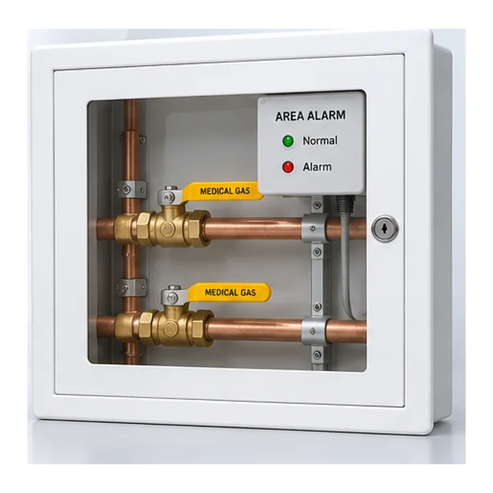
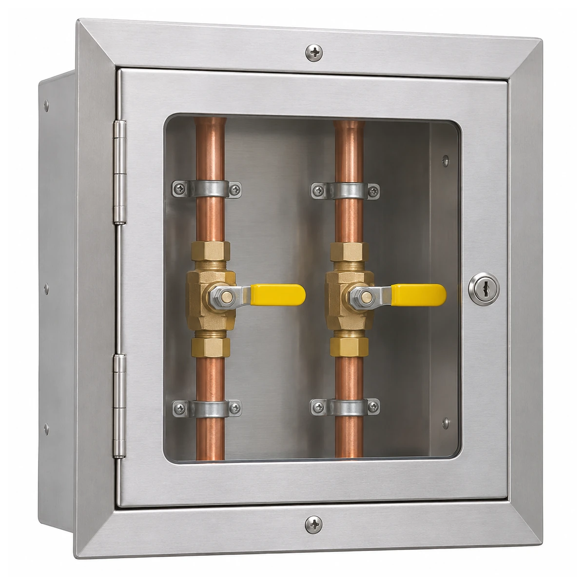
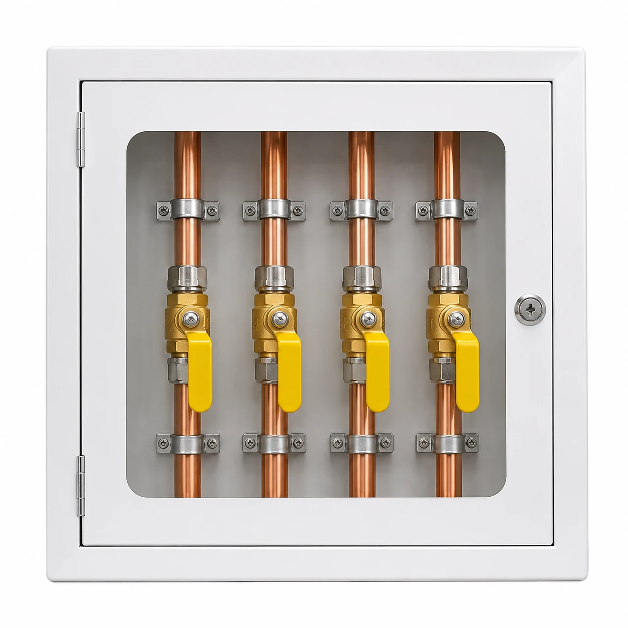
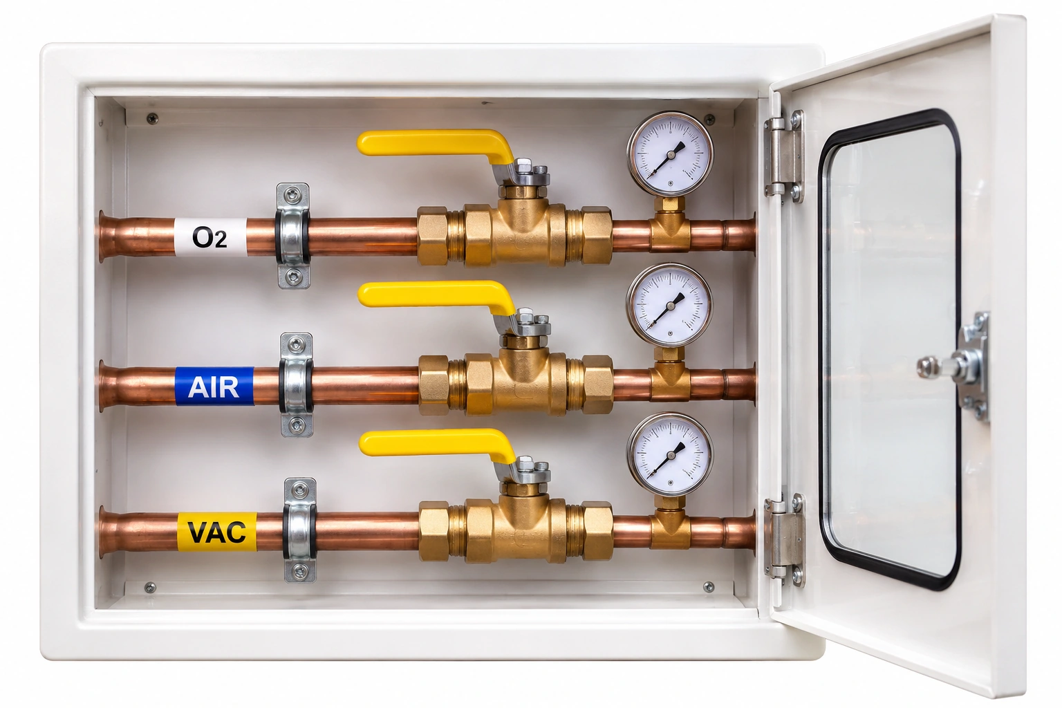
A service matrix should not stop at the outlet. Include the area valve service unit or zone control reference that serves each room. For every area valve zone, list its served room IDs and the responsible clinical area. A ward boundary on an architectural plan may not match an isolation boundary, and a renovation can change one without changing the other.
Cross-check the schedule against the zone drawing:
- Every required outlet belongs to a defined service and identified serving zone.
- A zone label corresponds to the correct room group and floor.
- The clinical team understands which locations would be affected by isolation.
- The location of the valve box remains accessible under the final building layout.
- The alarm and any monitoring interface are tied to the correct service/zone.
This is a document coordination exercise. Actual operating and isolation actions remain under the healthcare facility’s approved procedures.
Example of a controlled matrix row
The following is a format example, not a prescribed terminal count:
- Project: South Wing; Room: SW-2-014; Use: single-bed critical-care room.
- Proposed services: O2 — quantity pending clinical sign-off; medical air — quantity pending; vacuum — quantity pending.
- Mounting: bedhead panel; interface: approved country-specific terminal drawing reference.
- Valve zone: SW-L2-Z03; system drawing: MG-201 revision C.
- Demand worksheet: MG-CALC-02 revision B.
- Review: clinical lead pending; engineering approved for coordination only; procurement on hold.
A schedule that openly records “pending” is safer than one where an assumed quantity silently becomes an order.
Turn revisions into a change-control process
Room names and bedhead designs change during projects. Require a revision log showing previous quantity, proposed quantity, reason, impacted drawing IDs, likely effect on load and valve zoning, and approval decision. Mark superseded rows clearly. Do not permit a drawing update and a procurement spreadsheet to drift into separate realities.
An effective gate before ordering is: every terminal count has an approved room reference; every service has a defined connector family; every zone has a corresponding drawing; and all changes since the last approved issue have been evaluated.
What to send when requesting components
Send the schedule with room/terminal quantities, the approved interface details, zone valve schedule and drawing references. Separate the components that BWC Medgas may supply—medical gas outlets, zone valve boxes and related fittings—from plant design, installation and clinical verification responsibilities.
The supplier can then offer actual component models against a consistent set of inputs. Discuss a schedule-based MGPS component enquiry with BWC Medgas.
Frequently asked questions
Is one outlet per bed a standard rule?
No. Outlet count and services must follow the clinical room brief and applicable project requirements; room labels alone do not determine them.
Should a terminal schedule contain flow rates?
It should reference the approved design-demand document and any relevant performance requirements, while keeping terminal quantity and engineering load assumptions clearly distinct.