
Source alarm panels are often purchased by channel count: “eight-channel medical gas alarm.” The buyer may not know whether the specified signals indicate a source condition, a distribution pressure state, an equipment fault or a communications failure. Two devices with eight channels may serve completely different functional requirements.
An alarm and monitoring signal matrix solves this by identifying the actual function of every monitored event. This article addresses design coordination and project acceptance evidence; site alarm thresholds and operational responses must be approved by the responsible system and healthcare authorities.
Start with the required system events
Review the source architecture and plant control documentation. Identify which events the applicable design requires to be monitored and which must be relayed to local, central or building-management systems.
Typical categories for a design review may include source availability and status, an approved equipment fault, reserve-related condition, distribution pressure issue, gas-quality monitoring event or monitoring-path problem. The exact required set is specific to the system and jurisdiction. An illustrative list must not be mistaken for the definitive requirements of ISO 7396-1 or HTM 02-01.
Keep alarm purpose, measurement point and display destination in different columns.
The minimum useful matrix structure
Assign a unique tag, such as MG-O2-AL-017, and record:
- Gas/service and source asset ID.
- Event description in plain language.
- Initiating sensor/contact and physical measurement location.
- Signal type, interface and electrical characteristics approved by designers.
- Plant-local indication and any remote indication.
- Intended alarm categorization according to the adopted design specification.
- Responsible operational recipient and the related procedure ID.
- Controls/integration supplier for each signal handoff.
- Factory check, site check and integrated acceptance evidence reference.
- Outstanding issue, revision and final approval.
Do not copy a signal list from a different hospital and change only the building name.
Distinguish local control from hospital-wide indication
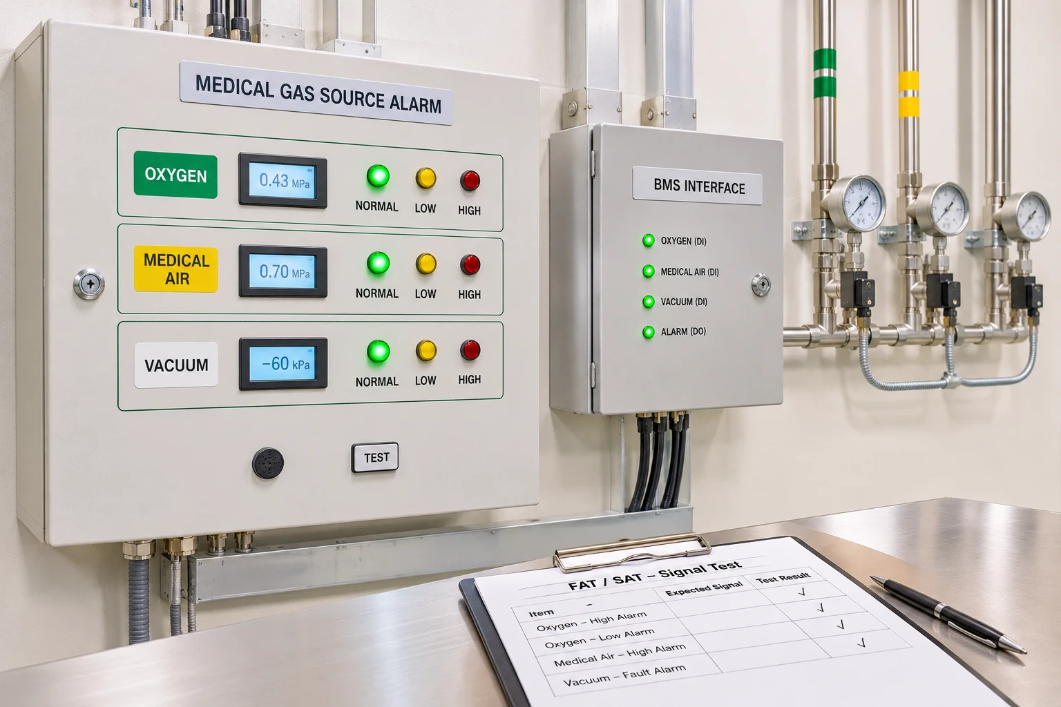
A plant's local control panel may have detailed maintenance diagnostics. The hospital may require a separate set of alarms or status indications at selected monitored locations. A BMS can support coordination but should not be presumed to replace any required medical gas alarm function without competent design and approval.
Define what the panel shall display, what constitutes alarm acknowledgment and what remains visible for operational response. These are project requirements, not decisions to be improvised during installation.
Clarify signal ownership across contractors
The source vendor might supply a dry contact or another approved output, while a separate alarm contractor provides the receiving device. A BMS contractor may supply communications infrastructure. Without a boundary schedule, each party can deliver a technically valid box that does not exchange the agreed information.
For each signal, write:
- Who supplies the sensor/initiating event.
- Who provides the physical/electrical output.
- Who supplies receiving inputs, wiring and configuration.
- Who witnesses functional verification.
- Who receives and acts on the event during operation.
Tie this to the system interface register and contractor responsibility matrix.
Factory versus site tests
Factory acceptance can confirm aspects of a panel or controls assembly before delivery; it cannot prove every installed hospital signal reaches the correct destination. Site and integrated acceptance evidence should demonstrate the relevant interfaces under the approved testing strategy.
The test register should identify signal tag, requirement, expected approved behavior, observed result, witness, date and defect closure. The appointed competent team conducts safe test procedures; this guide does not instruct personnel to deliberately interrupt critical medical gas supplies.
Example: false completeness from channel count
One bid says “12 channels, all gas types.” The project needs to distinguish two oxygen source events, a medical-air plant event, a vacuum-related event and defined remote interfaces at specific locations. Channel count alone does not confirm the right signal types, compatibility, annunciation or integration.
Ask for a line-by-line response to the approved matrix rather than accepting “complies” as a universal answer.
Prepare a supplier-readable RFQ
Issue drawings and the signal schedule showing interface boundaries, power requirements, location/mounting arrangements, labeling, reporting and expected evidence. Preserve the actual approved revision of the gas source diagram.
NHS HTM/SHTM guidance and ISO 7396-1 provide the broad context for monitoring and alarms in MGPS; the installed system must satisfy the project-specific requirements adopted by the responsible authority.
Relevant BWC Medgas products
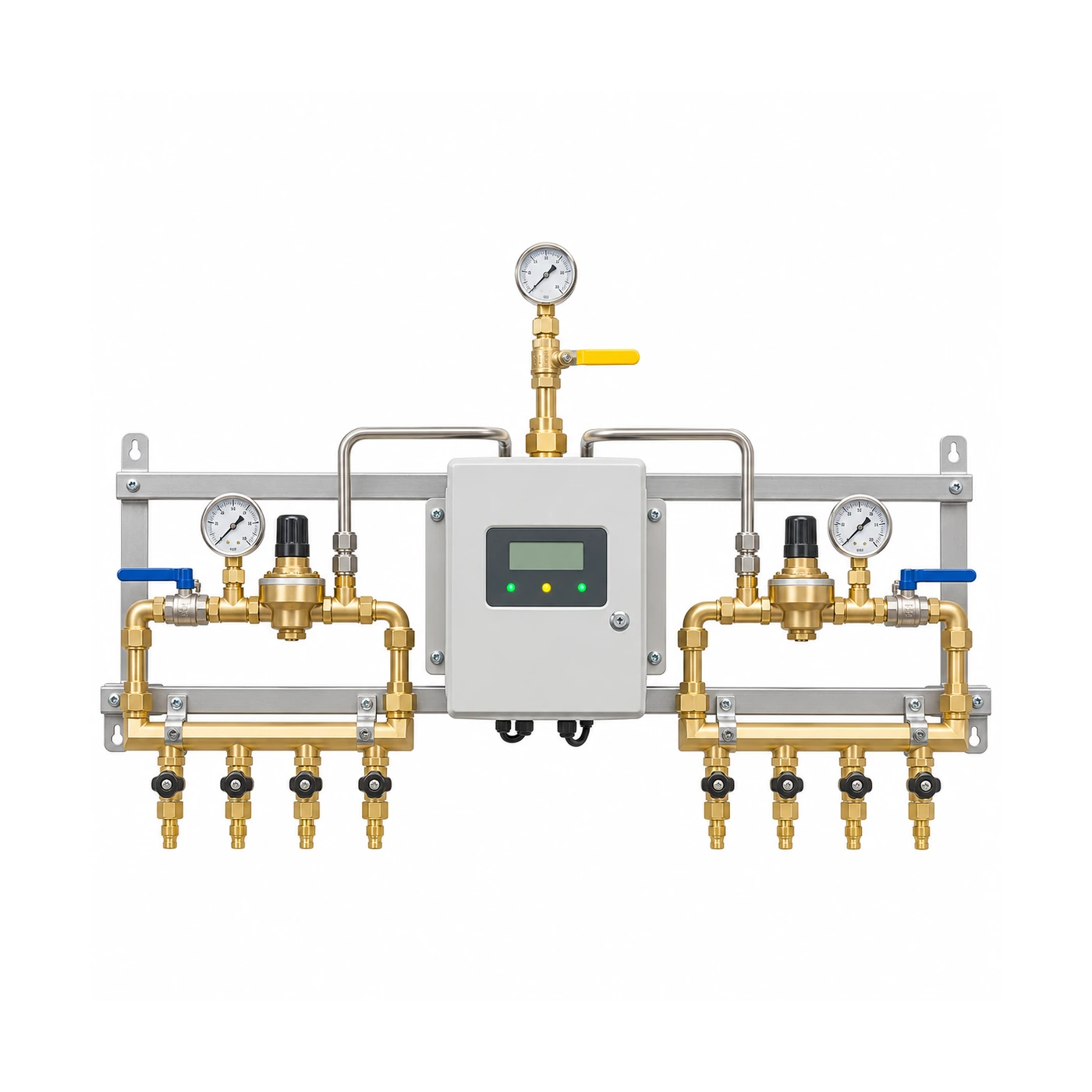
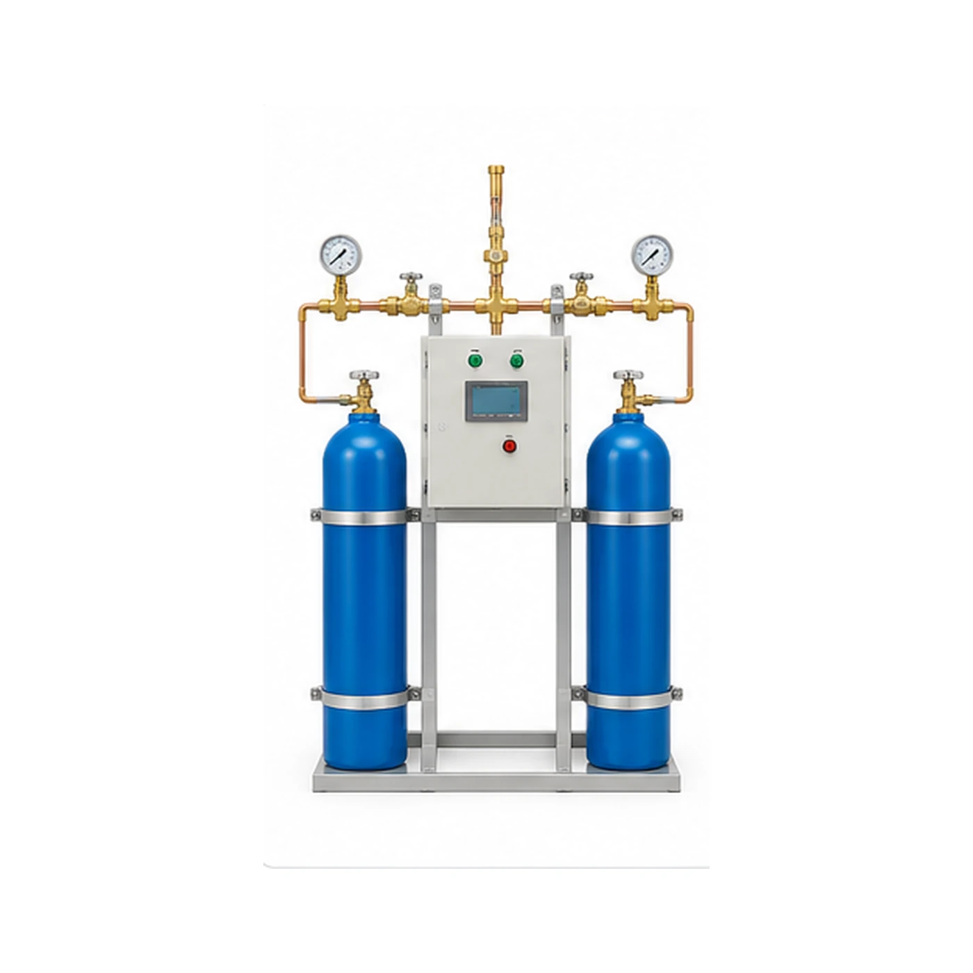
BWC provides selected medical gas alarm panels, zone valve boxes and related hardware. Compare BWC's exact model/interface data against the signal matrix, not against an unqualified request for “three gas alarms.”
Send an approved alarm/signal schedule to BWC Medgas.
FAQ
Can any eight-channel panel be used for any eight source signals?
No. Signal type, alarm function, intended use and integration requirements must match the design.
Does a green indicator at the control panel establish hospital-wide alarm acceptance?
No. The relevant site functionality, routing and evidence must also be verified.