
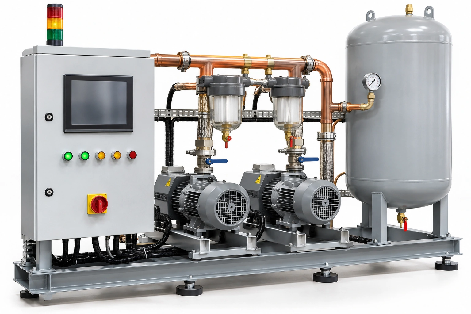
A hospital vacuum control panel may display pump run states, selected duty/standby positions, receiver readings, alarms and external signals. These are not interchangeable types of information. A green running light can show that a motor has been energized without proving delivered vacuum performance at the clinical network.
A vacuum-source cause-and-effect register ties the monitored physical condition to the right alarm category, receiving location and responsible hospital role.
Begin with a complete source functional specification
Record the source plant P&ID, manufacturer controls sequence, number and actual roles of pumping units, pressure sensors, filter condition monitoring and relevant power or communication paths. Identify which events are routine plant states, abnormal engineering conditions or required clinical area alarms.
ISO 7396-1:2016 governs monitoring and alarms for the MGPS vacuum pipeline. The operator must apply the relevant NHS HTM 02-01 (2026) or local adopted standard as appropriate.
Construct an event matrix with unambiguous identifiers
| Register field | Question | Verification |
|---|---|---|
| Source point | Which exact pump/receiver/sensor is monitored? | Model and P&ID |
| Event meaning | Physical condition or status, not an informal nickname? | Design specification |
| Normal/abnormal | Approved distinction and event priority? | Functional description |
| Receiver | Local, central, area or other specified alarm destination? | Alarm schedule |
| Fault representation | Missing power, failed sensor or communication loss? | Failure-mode evidence |
| Time and record | Is the event logged and identifiable? | Controller records |
| Response owner | Which estates/clinical party acts or escalates? | Operations manual |
| Test/witness | Approved method and site acceptance result? | Commissioning index |
Do not assume that the alarm system has been accepted merely because a panel can be silenced or a screen is bright.
Separate pump state and available suction
One pump running may be normal in a staged source plant; two pumps running may reflect increased demand or a control strategy, not necessarily a fault. The approved functional description must define what different run and standby states mean.
Likewise, a sensor alarm may indicate pressure/vacuum conditions at the receiver, not at every ward. Avoid generic labels like “vacuum alarm” that omit the actual point and condition.
Resilience and fault visibility
A well-documented system explains what authorized operators see if a sensor, controller, power supply or communications link becomes unavailable. A BMS or remote dashboard is not automatically a substitute for required on-site medical-gas alarm functions.
The event register should indicate which alarms must continue independently and how stale or invalid data is identified. Any fault-mode testing must be planned by qualified personnel and coordinated with clinical operations.
Example: standby not available, but no explicit event
A controller displays two pump icons as available, yet one pump has been removed for maintenance and the panel provides only a generic manual-override indicator. The operator may be unable to distinguish the intended standby configuration from an unavailable reserve.
The project should require model-specific signal definitions and an approved maintenance state in the final operating documentation. Do not recommend overriding controls or triggering pumps outside a permitted test plan.
Link plant tests with alarm tests
NHS Scotland SHTM 02-01 (2026) lists distinct medical vacuum plant and area/central alarm test evidence. One pump test does not establish that the event appears at the correct receiving panel with the correct meaning.
Maintain one test identifier per source event and receiving destination. Record deviations and accepted retests rather than overwriting the history.
Operational handover
The engineer's dossier should contain current firmware/configuration, approved cause/effect matrix, sensor measurement basis, event texts, central receiving map, escalation policy, supplier support contacts and restoration verification procedure.
Hospital estates staff should be able to trace a warning to the affected vacuum equipment without guessing from panel color.
BWC component relevance
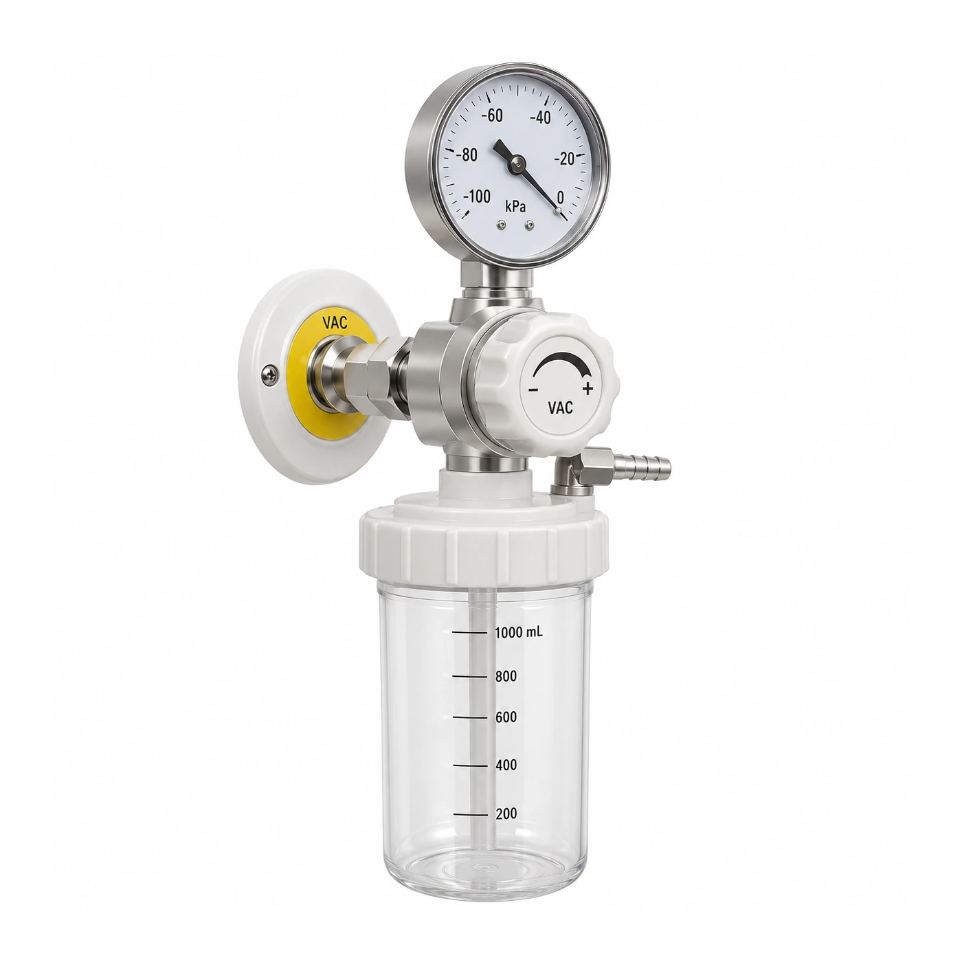
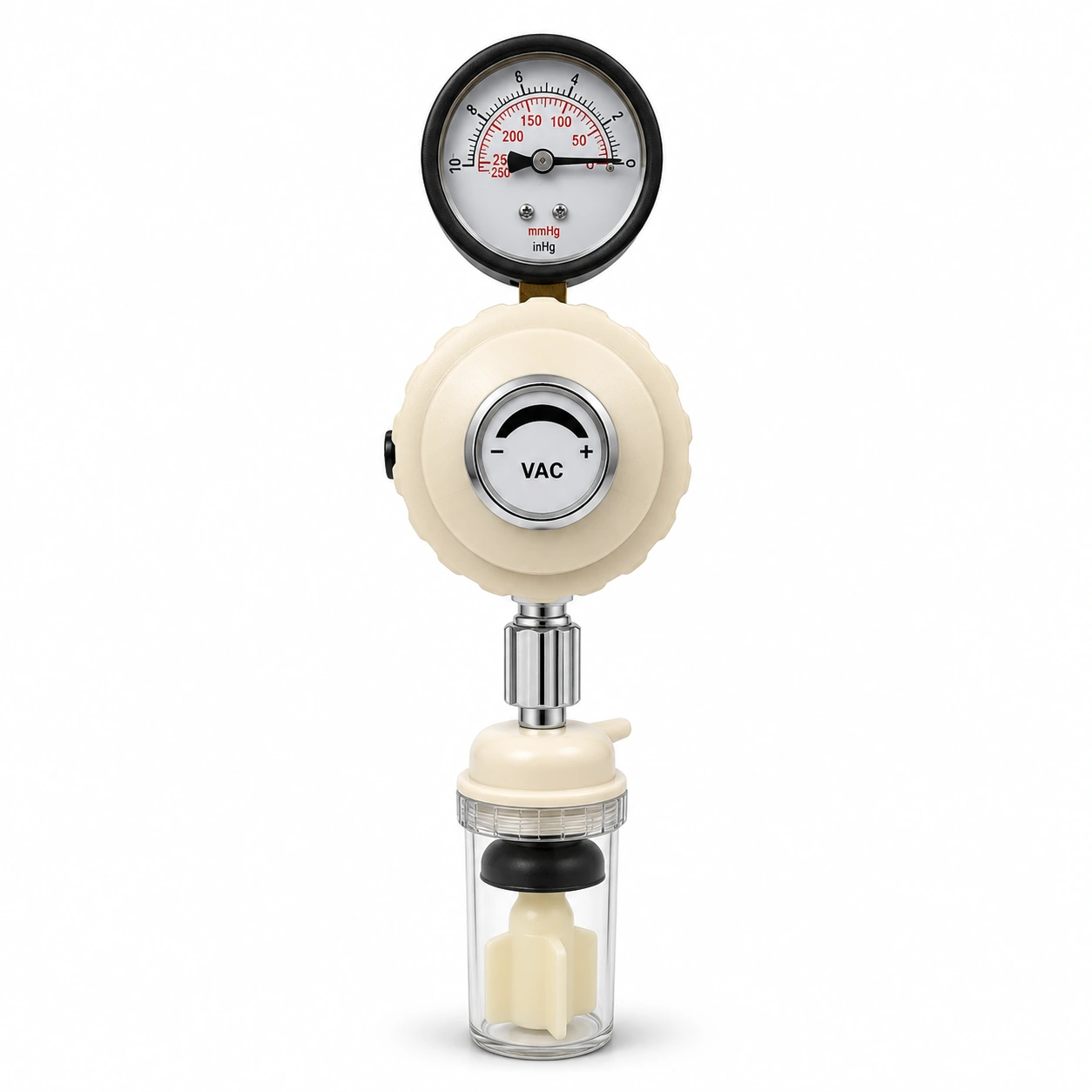
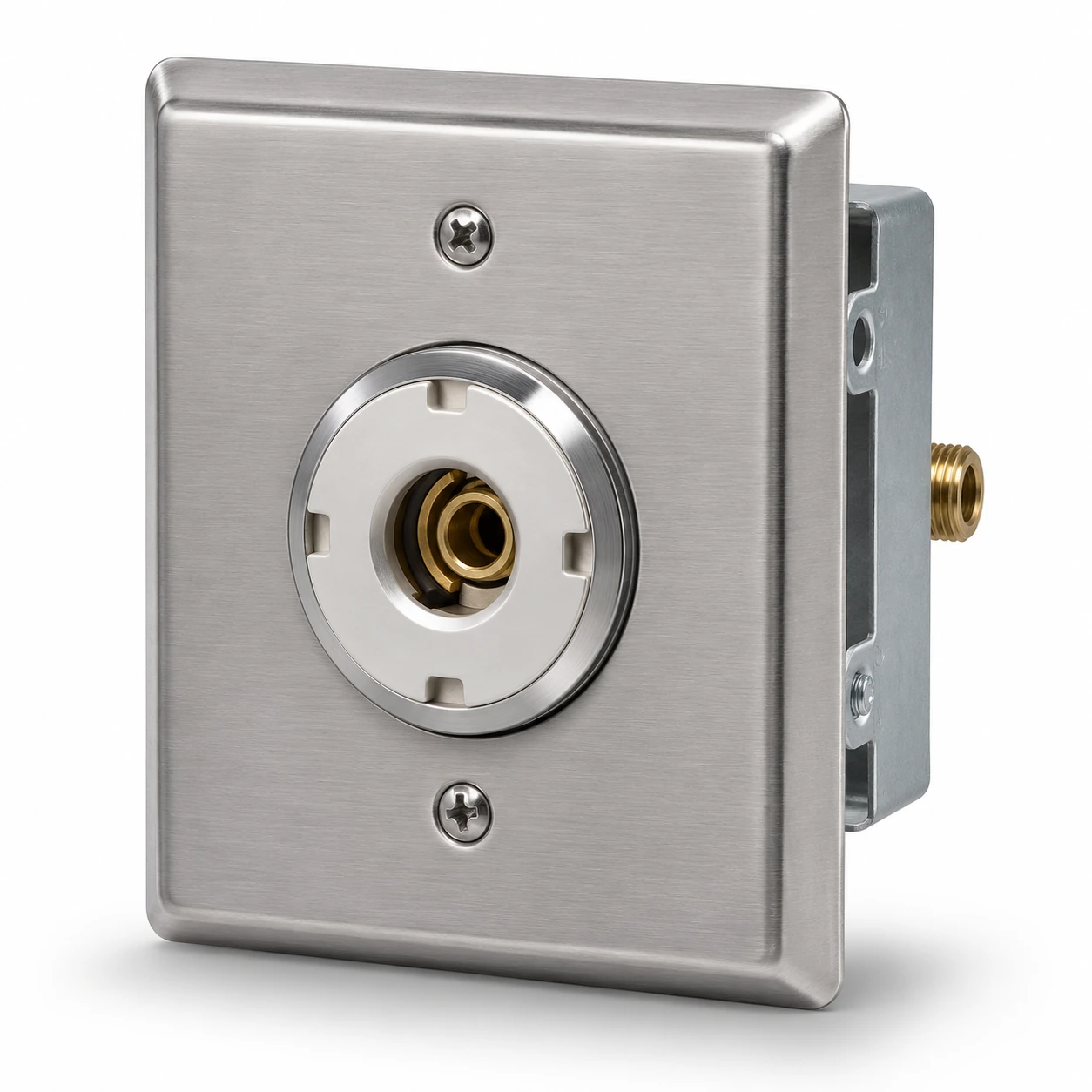
BWC Medgas supplies selected medical suction regulators and pressure/vacuum indication components for defined equipment and receiving interfaces. Source-plant controls, plant supply and live commissioning are separately contracted specialist responsibilities.
Submit an approved vacuum component or alarm interface request to BWC Medgas.
Frequently asked questions
Does a pump-running indication establish that medical vacuum is normal?
No. Machine state and delivered network performance are different facts.
Can a remote monitoring screen replace required hospital area and central alarms?
Not without formal adopted-code and engineering approval.