
Medical gas components do not exist in an empty drawing. They share hospital rooms, ceilings and service spaces with electrical systems, medical equipment, ventilation, fire systems, structural constraints and architectural finishes. A technically correct valve box can still be unusable if its door cannot open after a wall cabinet is installed.
MEP coordination should therefore focus on physical access, location ownership, interfaces and change control—not only on whether pipes collide in a 3D model.
Establish the MGPS coordination model
Begin with an approved clinical room schedule and system architecture. For every medical gas service, the design team should provide controlled routes and interfaces at the level appropriate to the project.
Agree which discipline owns each kind of model element: source equipment location, distribution routes, riser penetrations, valve enclosures, alarm panels, bedhead or pendant locations, and terminal connections.
In a BIM workflow, names and model colors alone are insufficient. Use unique asset IDs aligned to the equipment schedule and the final as-installed information.
Review what affects the patient-care location
A terminal unit can be correctly selected for its gas and still have the wrong practical location. Check the final furniture, bed or clinical equipment arrangement; the bedhead manufacturer’s layout; access for authorized maintenance; and the project’s accepted service outlet configuration.
For terminals installed in a modular bedhead or pendant, confirm who supplies the terminal and who is responsible for the mounting, inlet connection, support and finished assembly. The engineering record should refer to the approved product arrangement rather than an unverified 3D symbol.
Confirm service access before construction
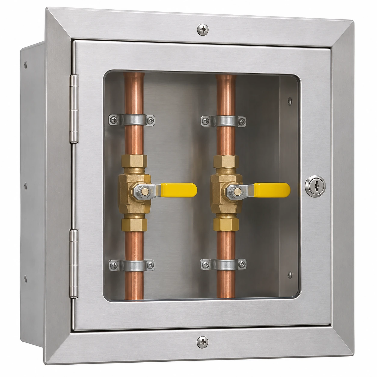
Create a list of equipment that requires physical access:
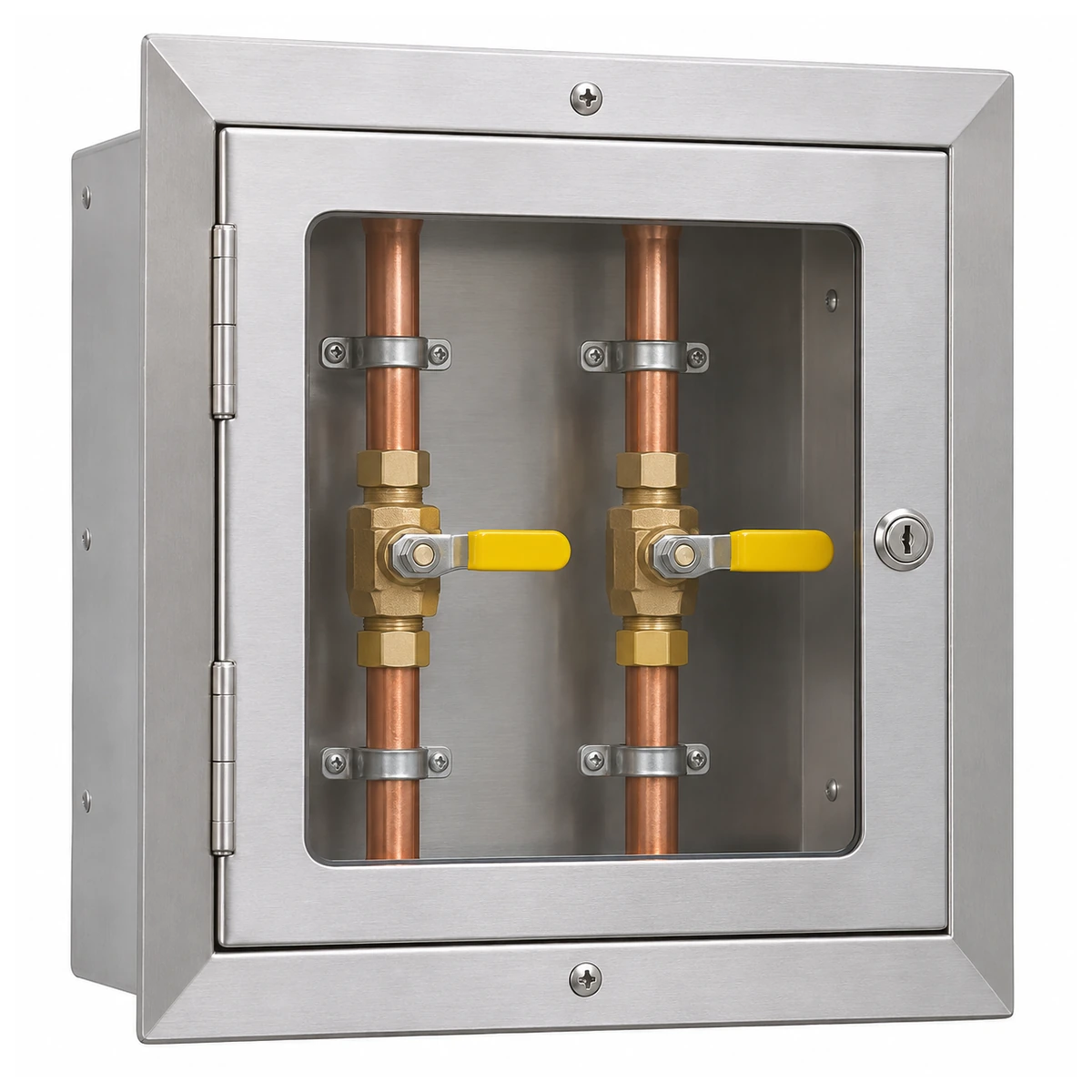
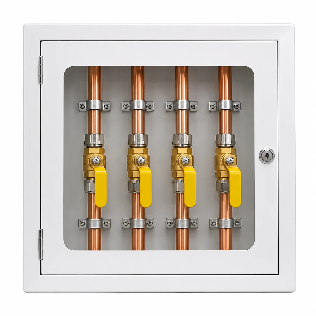
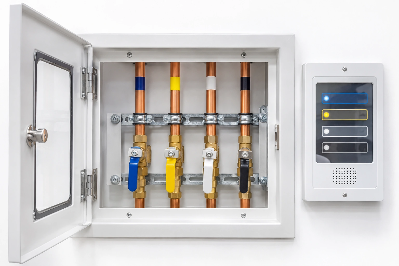
- Area valve boxes and isolation valves.
- Alarm panels and monitoring points.
- Line regulators and inspection locations.
- Pipeline identification and relevant accessible connections.
- Interfaces for maintenance/replacement of terminal assemblies.
Check door swing, adjacent cabinets, ceilings, service panels and other obstructions. A nominal clearance depicted in a drawing must be checked against the actual model, manufacturer instructions and local requirements.
Coordinate valve zoning with architecture
A valve zone boundary should match the approved clinical service arrangement, not simply the boundary between two architectural drawing sheets. If corridors or partitions move, confirm that access and identification remain logical and that the served-room list still reflects the actual installation.
In refurbishment work, include retained valves and existing service interfaces in the coordination model rather than modeling only new components.
Treat alarm interfaces as a multi-discipline subject
An alarm panel may involve sensing, gas/pressure monitoring, a power supply and communications interfaces. Define which contractor provides each interface, who supplies or validates the agreed signal information, and how the results will appear in the integrated system acceptance records.
Do not interpret the existence of a generic communication port as proof of compatibility with the building management system or hospital alarm workflows.
Resolve clashes with a documented decision
A useful coordination issue record contains:
- Issue ID and model/drawing references.
- Affected medical gas service and physical zone.
- Clash description and why it matters clinically or operationally.
- Proposed responsible party and design decision.
- Impacted component quantity, access, routing or service interface.
- Updated drawing revision and closure evidence.
A 3D clash marked “resolved” without a revised approved drawing may be an unresolved procurement problem.
Example: a wall cabinet blocks a valve box
An architectural change places a storage cabinet in front of a medical gas zone valve box. Relocating the cabinet may be simpler than redesigning the distribution, but the project must confirm continued access and any applicable clearance/identification requirements.
The correct response is a coordinated design decision with the clinical/operational owner. It is not to hide the box or omit it from the model.
Prepare supplier-ready data
When requesting gas outlets, area valve boxes, alarm panels, copper pipe fittings or other components from BWC Medgas, include relevant approved dimensional drawings, mounting arrangements, gas-specific interfaces and quantities.
This allows component pricing and factory drawings to align with the coordinated design. Discuss your MGPS MEP interface schedule with BWC Medgas.
Frequently asked questions
Does a clash-free BIM model prove an MGPS is ready?
No. Clinical requirements, gas-specific compatibility, testing and operational acceptance are separate from geometric coordination.
Who owns the connection between a bedhead and the medical gas pipeline?
The project must assign the design, supply, installation and verification responsibilities at that interface in its scope matrix.